
0826-1X1T-GJ-F 10/100BASE-T PoE+ (30W) Tab-Up RJ45 MagJack Connector
The Bel Fuse 0826-1X1T-GJ-F is a single-port (1x1) Integrated Connector Module (ICM) designed for rugged industrial Fast Ethernet and Power over Ethernet Plus (PoE+ / IEEE 802.3at) deployments. Featuring integrated magnetics with a 1CT:1CT turns ratio, an extended operating temperature range of -40°C to +85°C, and a standard Tab-Up profile, this connector delivers continuous power up to 720 mA @ 57 VDC (30 W) while ensuring 2250 VDC dielectric isolation.
Key Features of 0826-1X1T-GJ-F 30W PoE+ Magjack
- Ethernet Speed: 10/100BASE-T Fast Ethernet
- Power Delivery Rating: IEEE 802.3at PoE+ compliant (30W, 720 mA continuous @ 57 VDC; 1.2 A @ 57 VDC peak for 200 ms)
- Mechanical Orientation: Right Angle / Horizontal, Tab-Up (Latch Up)
- Operating Temperature: Industrial Grade -40°C to +85°C
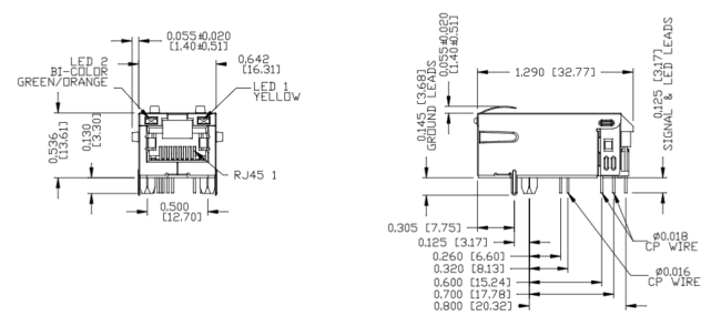
- Optical Status: Dual LED configuration — LED 1 (Yellow) & LED 2 (Bi-color Orange/Green)
- Dielectric Isolation: 2250 VDC HiPot isolation voltage (100% production tested)
- Compliance: RoHS Compliant, UL Recognized (Files #E196366 & #E169987), FCC cavity compliant
Detailed Electrical Specification
| Parameter | Specification Value | Test Condition / Notes |
|---|---|---|
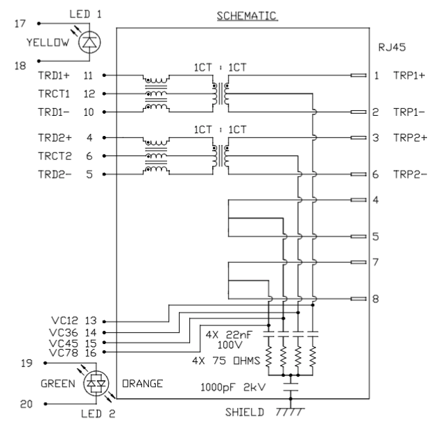
| Turns Ratio (TP1 & TP2) | 1CT : 1CT (±2%) | Transmit & Receive Channels |
| Open Circuit Inductance (OCL) | 350 μH Min. | @ 100 kHz, 100 mVrms, 11 mA DC Bias |
| Insertion Loss | -1.1 dB Max. (0.1–1 MHz) -0.8 dB Max. (1–65 MHz) -1.2 dB Max. (65–100 MHz) |
Across Operating Frequency |
| Return Loss | -18 dB Min. (0.5–40 MHz) -(12 + 20 log(f/80 MHz)) dB (40–100 MHz) |
System Impedance: 100 Ω |
| Common Mode Rejection (CM to CM) | -30 dB Min. | 100 kHz–100 MHz |
| Common Mode to Differential Mode Rejection (CM to DM) | -35 dB Min. | 100 kHz–100 MHz |
| Balanced DC Line Current | 720 mA Max. Continuous @ 57 VDC 1.2 A Max. for 200 ms @ 57 VDC |
Designed for IEEE 802.3at PoE+ Applications |
| High Potential (HiPot) Isolation | 2250 VDC | 100% Production Tested |
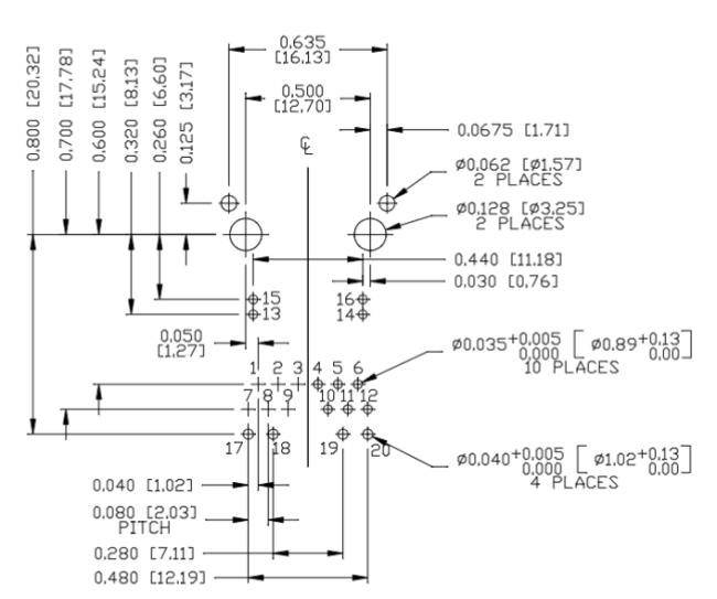
0826-1X1T-GJ-F 1X1 MagJack Drawing
Mechanical, Housing & Manufacturing Specifications
- Housing Material: High-temperature Thermoplastic PA, Black, Flammability Rating UL 94V-0.
- Contact Area: 50 micro-inches hard gold plating over 30 micro-inches nickel underplate for maximum mating reliability.
- Shield Construction: Copper alloy with continuous nickel plating; ground leads are pre-solder dipped to improve wave solder joint integrity.
- Overall Footprint Dimensions: Length: 1.290" [32.77 mm] × Width: 0.642" [16.31 mm] × Height: 0.536" [13.61 mm].
- Panel Cutout Recommendation: Suggested bezel opening is 0.672" [17.07 mm] wide × 0.551" [14.00 mm] high.
- Soldering Profile: Recommended for standard wave soldering; peak wave temperature 260°C Max for 10 seconds Max.
- Standard Packaging: 40 pcs per tray, 10 trays per master carton box (400 pcs/carton).
Engineering Integration & PCB Layout Rules of 0826-1X1T-GJ-F ICM
1. Bob Smith Termination and Isolation
The unit integrates four internal 75 Ω termination resistors, four 22 nF / 100 V DC-blocking capacitors, and a 1000 pF / 2 kV high-voltage capacitor connected to the outer shield as part of the Bob Smith termination network.
When routing the PCB, keep high-speed Ethernet differential pairs away from noisy power traces and switching nodes, particularly beneath and around the connector keep-out area. Maintaining separation from high-dV/dt and high-current paths helps reduce common-mode noise coupling and preserves signal integrity.
2. PoE+ Power Path Routing
The PoE power paths are brought out through dedicated VC connections on Pins 13, 14, 15, and 16. These pins provide access to the relevant Ethernet cable-pair power paths for external PoE PD or PSE circuitry.
Use sufficiently wide copper traces or planes for the PoE current path and size the PCB copper according to the required current, copper thickness, allowable temperature rise, and routing length. The reference device supports up to 720 mA balanced DC line current continuously at 57 VDC, so the surrounding PCB power path should be designed with adequate current-carrying margin.
Avoid narrow neck-downs, excessive via resistance, and unnecessary routing transitions in the PoE current path, as these can increase localized heating and voltage drop.
3. EMI Shield Grounding
Ensure that all shield and retention tabs make a short, low-impedance connection to the intended chassis ground or peripheral shield-ground structure.
Proper shield grounding helps provide an effective path for common-mode noise and improves EMI performance at the Ethernet cable interface. Keep shield-current paths short and direct, and avoid routing shield return currents through sensitive digital or analog ground regions whenever possible.
The final grounding method should be coordinated with the system-level chassis, PCB ground architecture, ESD protection strategy, and EMC requirements.
0826-1X1T-GJ-F 10/100Base-T PoE+ RJ45 Connector Application
- Industrial Automation: Machine vision cameras, programmable logic controllers (PLCs), remote I/O modules requiring PoE power.
- Smart Building & Security: Outdoor PTZ IP surveillance cameras, PoE-powered biometric access controllers.
- Harsh Networking Environments: Industrial Ethernet switches, outdoor wireless access points (WAPs), IoT edge gateways operating in extreme thermal conditions (-40°C to +85°C).
FAQs About 0826-1X1T-GJ-F RJ45 Magjack
Q1: Does the Bel Fuse 0826-1X1T-GJ-F support Gigabit Ethernet?
No. The 0826-1X1T-GJ-F is engineered specifically for 10/100BASE-T (Fast Ethernet) networks. If your application requires Gigabit speeds (1000BASE-T), you must select an 8-channel/4-pair Gigabit MagJack series rather than this 2-pair variant.
Q2: What is the maximum PoE power supported by 0826-1X1T-GJ-F?
The connector supports PoE+ (IEEE 802.3at / Type 2) delivering up to 30 Watts. It handles a balanced continuous line current of 720 mA @ 57 VDC and peak inrush current of up to 1.2 A @ 57 VDC for 200 ms.
Q3: What is the tab orientation for this RJ45 connector?
The 0826-1X1T-GJ-F features a Tab-Up (Latch Up) port orientation. This design allows easy cable disengagement from the top, which is particularly beneficial for DIN-rail and baseboard mounted hardware where bottom clearances are limited.
Q4: How do the LEDs operate on 0826-1X1T-GJ-F?
LED 1 (Pins 17/18) is a single-color yellow LED. LED 2 (Pins 19/20) is a bi-color LED emitting orange when Pin 19 is positive and green when Pin 20 is positive. Both operate at standard 20 mA forward drive currents.
Get in Touch
Have questions about our products or want to discuss a custom order? Our team is ready to help you.