
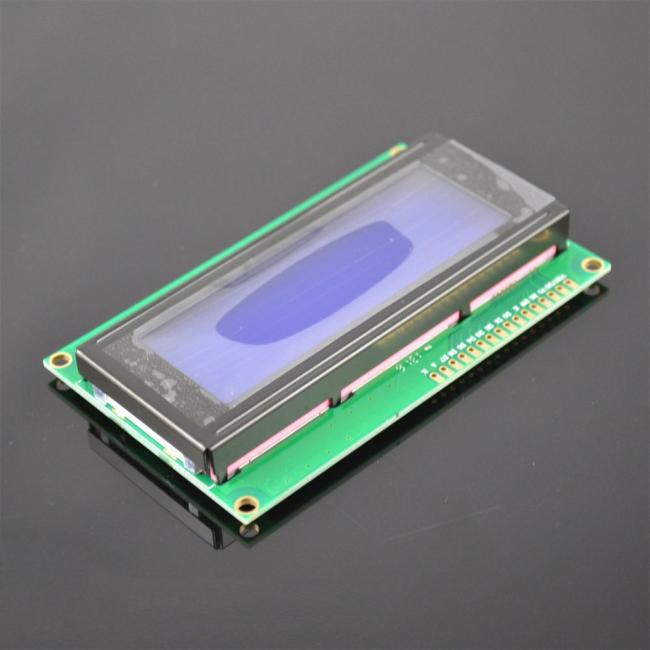
2004A 20x4 5V Character LCD Display Module for Arduino SPLC780 Controller Blue Backlight
2004A 20x4 5V Character LCD Display Module for Arduino SPLC780 Controller Blue Backlight
Specifications
1. Low Prices Direct From Factory Suppliers.
2.High Quality With Global Standards.
Description:
Use your solderless breadboard and wire jumpers to make these connections:
|
LCD Pin |
Connect to |
|
1 (VSS) |
GND pin* |
|
2 (VDD) |
+ 5v pin |
|
3 (contrast) |
Resistor or potentiometer to GND pin* |
|
4 RS |
pin 12 |
|
5 R/W |
pin 11 |
|
6 Enable |
pin 10 |
|
7 No connection |
|
|
8 No connection |
|
|
9 No connection |
|
|
10 No connection |
|
|
11 (Data 4) |
pin 5 |
|
12 (Data 5) |
pin 4 |
|
13 (Data 6) |
pin 3 |
|
14 (Data 7) |
pin 2 |
|
15 Backlight + |
Resistor to pin 13** |
|
16 Backlight GND |
GND pin* |
*Use a breadboard rail to make multiple connections to the GND pin for Arduino
*For potentiometer connection, use the potentiometer's center pin and either of the other pins to make the connection from LCD pin 3 to Arduino GND
** A current limiting resistor or potentiometer (40 Ohm minimum) should be used to avoid excessive current. It should look something like this:
Software
Here is the driver code:/* ------------------------------------------------------------------------------- */
// character LCD example code
// www.hacktronics.com
#include <LiquidCrystal.h>
// Connections:
// rs (LCD pin 4) to Arduino pin 12
// rw (LCD pin 5) to Arduino pin 11
// enable (LCD pin 6) to Arduino pin 10
// LCD pin 15 to Arduino pin 13
// LCD pins d4, d5, d6, d7 to Arduino pins 5, 4, 3, 2
LiquidCrystal lcd(12, 11, 10, 5, 4, 3, 2);
int backLight = 13; // pin 13 will control the backlight
void setup()
{
pinMode(backLight, OUTPUT);
digitalWrite(backLight, HIGH); // turn backlight on. Replace 'HIGH' with 'LOW' to turn it off.
lcd.begin(20,4); // columns, rows. use 16,2 for a 16x2 LCD, etc.
lcd.clear(); // start with a blank screen
lcd.setCursor(0,0); // set cursor to column 0, row 0 (the first row)
lcd.print("Hello, World"); // change this text to whatever you like. keep it clean.
lcd.setCursor(0,1); // set cursor to column 0, row 1
lcd.print("keyes");
// if you have a 4 row LCD, uncomment these lines to write to the bottom rows
// and change the lcd.begin() statement above.
//lcd.setCursor(0,2); // set cursor to column 0, row 2
//lcd.print("Row 3");
//lcd.setCursor(0,3); // set cursor to column 0, row 3
//lcd.print("Row 4");
}
void loop()
{
}
/* ------------------------------------------------------------------------------- */
You will now have a folder called LCD_example
Start the Arduino software and load the example program by clicking File->Sketchbook->Open
Navigate to the LCD_example folder and select the ?LCD_example.pde? file.
Transfer the program to your Arduino by clicking the ?Upload to I/O board? button. After uploading, on the LCD you should see:
Hello, World
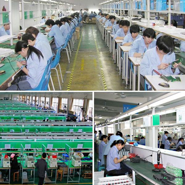
PHOTOS:
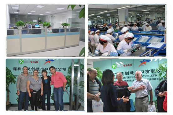
Our Team:
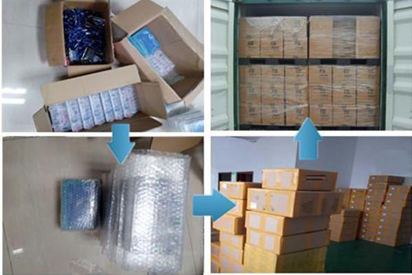
Packing&Shipping:
Awards:
FAQ:
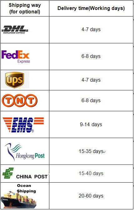
1. What is the delivery time?
Normally, 1-5 workdays after payment;
Special requirement orders, delivery time is negotiable.
2.If the products can’t work after receiving it,what should I do?
We will replace new items for you at once, and respect your final decision for wrong goods.
3.If the products don’t meet my demand after I received it,can I return it?
Yes,no problem.
You can return back to us, we will refund your full payment.
Get in Touch
Have questions about our products or want to discuss a custom order? Our team is ready to help you.