
120V Boot, 4A Peak, High FrequencyHigh-side And Low-side Driver Integrated Circuit IC Chip
Price:
Negotiable
MOQ:
1000PCS
Delivery Time:
3weeks
Brand:
UCHI
Product Description
120V Boot, 4A Peak, High FrequencyHigh-side And Low-side Driver Integrated Circuit IC Chip
The SGM48211 is a half-bridge MOSFET driver with4A peak source and sink output current capability,which makes it possible to drive large power MOSFETswith minimized switching losses. The two channels ofhigh-side and low-side are totally independent with 3ns(TYP) delay matching between the turn-on and turn-offof each other.
The maximum withstanding voltage of the input stageof SGM48211 is 20V. Due to the -10VDC voltageendurance capacity of its input stage, the driver hasenhanced robustness and can be interfaced to pulsetransformers directly without using rectifier diodes. Witha wide input hysteresis, the device can receive analogor digital PWM signals with improved noise immunity.A 120V rated bootstrap diode is integrated internally tosave the external diode and reduce PCB dimensionsize.
Under-voltage lockout (UVLO) is integrated in both thehigh-side and the low-side drivers. The output of eachchannel is forced low if the corresponding drivingvoltage falls below the specified threshold.
The SGM48211 is available in Green SOIC-8, SOIC-8(Exposed Pad) and TDFN-4×4-8AL packages.
Key Features
● Wide Operating Range: 8V to 17V
● Drive Two N-MOSFETs Configured in Half Bridge
● Maximum Blocking Voltage: 120V DC
● Integrated Internal Bootstrap Diode for CostSaving
● 4A Peak Sink and Source Currents
● -10V to 20V Tolerance of Input Pins
● COMS/TTL Compatible Inputs
● 6.5ns (TYP) Rise Time and 4.5ns (TYP) Fall Timewith 1000pF Load
● Propagation Delay Time: 31ns (TYP)
● Delay Matching: 3ns (TYP)
● UVLO Functions for Both High-side and Low-sideDrivers
● -40℃ to +140℃ Operating Junction TemperatureRange
● Available in Green SOIC-8, SOIC-8 (Exposed Pad)and TDFN-4×4-8AL Packages
Applications
Power Converters in 48V or Lower Systems Used inTelecom, Datacom, Portable Storage, etc.
Half-Bridge, Full-Bridge, Push-Pull, Synchronous-Buckand Forward Converters
Synchronous Rectifiers
Class-D Audio Amplifiers
Half-Bridge, Full-Bridge, Push-Pull, Synchronous-Buckand Forward Converters
Synchronous Rectifiers
Class-D Audio Amplifiers
Typical Application
![]()
The capacitance value of the bootstrap capacitor isrecommended to be no larger than 1µF to preventexcessive transient current breakdown of the bootstrapdiode when charging the bootstrap capacitor.
If the QG of the power transistor is particularly large andrequires a capacitance greater than 1µF, it isrecommended to connect a resistor directly on the HBpin in series with the bootstrap capacitor to reduce thetransient current. A 1Ω to 2Ω series resistor isrecommended. It is important to note that this seriesresistance also increases the total turn-on resistance.
If it is not possible to increase the series resistor, it isrecommended to add an external Schottky diodebetween the VDD and HB pins in parallel with the internal diode to share the transient current and reducethe effect of the transient current on the body diode. ASchottky diode like S115FP should be selected whenVF ≤ 0.8V @100mA.
A larger di/dt will generate a larger negative voltage onthe HS pin. Adding a RHS resistor can limit the peak ofthe negative voltage. If the negative voltage cannot besuppressed with the external RHS, it is recommended toadd a Schottky diode between HS and VSS to clampthe negative voltage. Connect the diode between HSpin and VSS pin directly as shown in Figure 1. Itsminimum blocking voltage should be larger than themaximum positive voltage of the half bridge.
Pin Configurations
![]()
Pin Description
![]()
Product Selection Guid

The capacitance value of the bootstrap capacitor isrecommended to be no larger than 1µF to preventexcessive transient current breakdown of the bootstrapdiode when charging the bootstrap capacitor.
If the QG of the power transistor is particularly large andrequires a capacitance greater than 1µF, it isrecommended to connect a resistor directly on the HBpin in series with the bootstrap capacitor to reduce thetransient current. A 1Ω to 2Ω series resistor isrecommended. It is important to note that this seriesresistance also increases the total turn-on resistance.
If it is not possible to increase the series resistor, it isrecommended to add an external Schottky diodebetween the VDD and HB pins in parallel with the internal diode to share the transient current and reducethe effect of the transient current on the body diode. ASchottky diode like S115FP should be selected whenVF ≤ 0.8V @100mA.
A larger di/dt will generate a larger negative voltage onthe HS pin. Adding a RHS resistor can limit the peak ofthe negative voltage. If the negative voltage cannot besuppressed with the external RHS, it is recommended toadd a Schottky diode between HS and VSS to clampthe negative voltage. Connect the diode between HSpin and VSS pin directly as shown in Figure 1. Itsminimum blocking voltage should be larger than themaximum positive voltage of the half bridge.
Pin Configurations

Pin Description

Product Selection Guid
| Part Number |
Number
of
Channels
|
Output Peak
Current
(A)
|
Vcc
(V)
|
Rise
Time
(ns)
|
Fall
Time
(ns)
|
Logic Low
Input Voltage
(V)
|
Logic High
Input Voltage
(V)
|
Input
Hysteresis
(V)
|
ICC Typ
(mA)
|
Packag
|
Features |
|---|---|---|---|---|---|---|---|---|---|---|---|
|
SGM48005
|
1 |
9/12
|
3 ~ 15
|
2.9
|
3.6
|
1.2 | 2.4 | 0.12 | 1 |
TSSOP-14
|
Zero Overshoot, Large Swing SiC & IGBT Driver with Precision Dual Power Rail Generation Circuit
|
|
SGM48010
|
1 |
8/12
|
4.5 ~ 20
|
10 | 10 | 0.9 | 2.5 | 0.45 | 0.13 |
TDFN-2×2-6L
|
Single-Channel High Speed Low-side Gate Driver
|
|
SGM48013C
|
1 |
8/13
|
4.5 ~ 20
|
7 | 8 | 0.7 | 2.5 | 0.45 | 0.09 |
SOT-23-5
|
Single-Channel High Speed Low-side Gate Driver
|
|
SGM48017C
|
1 |
8/13
|
4.5 ~ 20
|
7 | 8 | 0.7 | 2.5 | 0.45 | 0.09 |
SOT-23-5
|
Single-Channel High Speed Low-side Gate Driver
|
|
SGM48018C
|
1 |
8/13
|
4.5 ~ 20
|
7 | 8 | 0.7 | 2.5 | 0.45 | 0.09 |
SOT-23-5
|
Single-Channel High Speed Low-side Gate Driver
|
|
SGM48019C
|
1 |
8/13
|
4.5 ~ 20
|
7 | 8 | 0.7 | 2.5 | 0.45 | 0.09 | SOT-23-5 |
Single-Channel High Speed Low-side Gate Driver
|
|
SGM48209
|
2 |
4/5
|
8 ~ 17
|
6.5 | 4.5 | 1.5 | 2.25 | 0.7 | 0.13 |
SOIC-8,TDFN-4×4-8AL
|
120V Boot, 4A Peak, High Frequency High-side and Low-side Driver
|
|
SGM48211
|
2 |
4/5
|
8 ~ 17
|
6.5 | 4.5 | 1.5 | 2.25 | 0.7 | 0.13 |
SOIC-8,SOIC-8 (Exposed Pad),TDFN-4×4-8AL
|
120V Boot, 4A Peak, High Frequency High-side and Low-side Driver
|
|
SGM48510
|
1 |
11/6
|
4.5 ~ 24
|
4 | 4 |
1.3†
|
2.1†
|
0.8 | 0.5 |
TDFN-2×2-8AL,SOIC-8
|
11A High Speed Low-side MOSFET Driver
|
|
SGM48520
|
1 |
6/4
|
4.75 ~ 5.25
|
0.55 | 0.48 | 0.055 |
WLCSP-0.88×1.28-6B,TDFN-2×2-6AL
|
5V Low-side GaN and MOSFET Driver
|
|||
|
SGM48521
|
1 |
7/6
|
4.5 ~ 5.5
|
0.5 | 0.46 |
1.4†
|
2.15†
|
0.75 | 0.075 |
WLCSP-0.88×1.28-6B,TDFN-2×2-6AL
|
5V Low-side GaN and MOSFET Driver
|
|
SGM48521Q
|
1 |
7/6
|
4.5 ~ 5.5
|
0.5 |
0.46 |
1.4†
|
2.15†
|
0.75 |
0.075††
|
WLCSP-0.88×1.28-6B,TDFN-2×2-6DL
|
Automotive, 5V Low-side GaN and MOSFET Driver
|
|
SGM48522
|
2 |
7/6
|
4.5 ~ 5.5
|
0.75
|
0.56 |
1.4†
|
2.1†
|
0.7 | 0.1 |
TQFN-2×2-10BL
|
Dual-Channel 5V Low-side GaN and MOSFET Driver
|
|
SGM48522Q
|
2 | 7/6 |
4.5 ~ 5.5
|
0.72
|
0.57 |
1.4†
|
2.1†
|
0.7 | 0.05 |
TQFN-2×2-10AL
|
Automotive, Dual-Channel 5V Low-side GaN and MOSFET Driver
|
|
SGM48523
|
2 |
5
|
4.5 ~ 18
|
8 | 8 |
1.2†
|
2†
|
0.8 | 0.036 |
SOIC-8,MSOP-8 (Exposed Pad),TDFN-3×3-8L
|
Dual-Channel High Speed Low-side Gate Driver
|
|
SGM48523C
|
2 |
5
|
8.5 ~ 18
|
7 | 7 |
1.2†
|
2.1† | 0.9 | 0.075 |
SOIC-8,MSOP-8 (Exposed Pad),TDFN-3×3-8L
|
Dual-Channel High Speed Low-side Gate Driver
|
|
SGM48524A
|
2 |
5
|
4.5 ~ 18 | 8 | 8 |
1.2†
|
2† | 0.8 | 0.038 |
SOIC-8,MSOP-8 (Exposed Pad),TDFN-3×3-8L
|
Dual-Channel High Speed Low-side Gate Driver
|
Notes: † Typical Values @ 25℃
†† Max Value
Integrated circuits (ICs) serve as the foundation of modern electronics, offering small size, low power consumption, strong performance and high reliability. They are widely used in consumer electronics, industrial applications, communications, automotive electronics, medical equipment, and aer ospace/defense systems.

Uchi Electronics provides high-performance analog and mixed-signal processing solutions for industrial automation, new energy, automotive, communications, computing, consumer electronics and medical equipment applications.
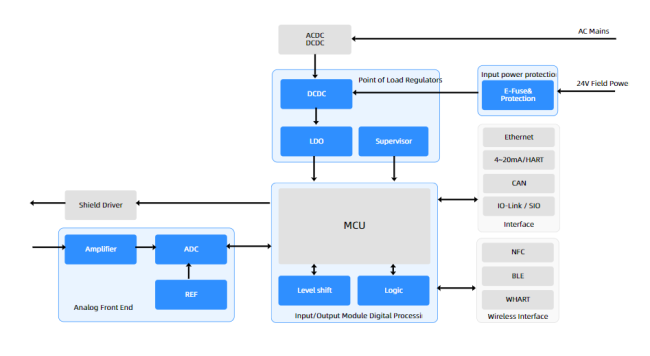
This solution demonstrates the integrated circuit application of capacitive level transmitters. For assistance selecting the right product, please contact our technical support team.
Similar Products
Get in Touch
Have questions about our products or want to discuss a custom order? Our team is ready to help you.
Company
Guangdong Uchi Electronics Co.,Ltd
Location
Room 810, Unit 2, Building 5, Huixing Commercial Center, Dongsheng Road No.1, Zhongshan Dong, Shilong Town Dongguan, GUANGDONG, 523326 CN
Contact Person
Anna