
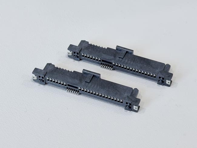
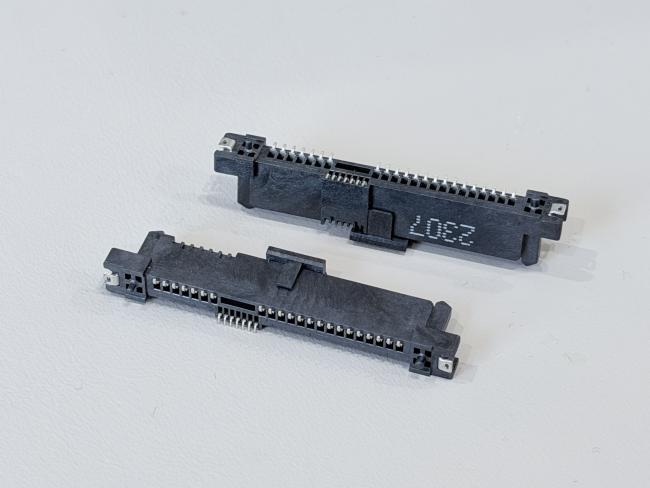
SAS 29P SMT Female Connector 1.27mm Pitch, Type 45 Version with 30U" Gold-Plated Contacts for High-Speed Electronic Signal & Power PCB Connection
• Free samples available for quality evaluation.
• Support for both OEM & ODM customization.
• Trade Terms: EXW, FOB, CIF, CPT, etc.
This SAS 29P SMT female connector is a high-reliability electronic connector designed for dense PCB layouts and high-speed SAS 4.0 signal transmission. With a 1.27mm pitch and full surface-mount design, it supports automated reflow soldering and compact routing in server, storage, automotive and industrial systems.
The contact system uses phosphor bronze C5191-H terminals with a robust three-layer plating structure: 50µ" nickel underplate for corrosion protection, 30µ" gold on the contact area to maintain low contact resistance for high-speed differential pairs, and 80µ" matte tin on the solder area for strong, reliable joints to PCB pads. A brass positioning peg and SUS304 metal clips provide extra mechanical retention, improving resistance to vibration and shock in demanding applications.
Electrically, the connector is rated at 1.5A @ 40VAC, with contact resistance ≤30mΩ, insulation resistance ≥1000MΩ, and a withstand voltage of 500VAC per minute. Mechanically, it offers controlled mating and unmating forces and up to 500 mating cycles on the backplane side according to EIA 364-09. A 48-hour salt-spray test on the gold area further verifies long-term reliability in harsh environments.
Using halogen-free, UL94-V0 LCP housing and fully RoHS 2.0 compliant materials, this SAS 29-pin SMT female connector is ideal for customized wire cable assemblies, high-density server backplanes, and other electrical power and signal transmission applications that require stable performance and long service life.

| Product Type | SAS 29P SMT straight female connector, 30U" gold-plated |
| Interface Series | SAS series, 29-pin female |
| Number of Positions | 29 pins (7 + 7 signal pins, 15 power/ground pins) |
| Pitch of Housing | 1.27mm (SAS standard pitch) |
| Gender | Female connector |
| Mounting Style | SMT (surface-mount) to PCB |
| Mechanical Retention | 2 × metal clips + 1 × positioning peg |
| Rated Current / Voltage | 1.5A @ 40VAC |
| Operating Temperature | –20°C to +85°C |
| Contact Resistance | ≤ 30mΩ (Max) |
| Insulation Resistance | ≥ 1000MΩ (Min) |
| Withstand Voltage | 500VAC / minute |
| Mating Force | Backplane ≤ 25N Max |
| Unmating Force | Backplane ≥ 5N Min |
| Mating Durability | Up to 200 cycles/hour; backplane 500 cycles max (per EIA 364-09) |
| Salt Spray Test | Gold-plated area ≥ 48 hours |
| Terminal Base Material | Phosphor Bronze C5191-H, t = 0.25mm (TS-C07F-M22 / TS-007F-M09 / TS-C15F-M14) |
| Terminal Plating – Underlayer | Ni 50µ" min plated on terminal |
| Terminal Plating – Contact Area | Au 30µ" min plated on contact area |
| Terminal Plating – Solder Area | Matte Sn 80µ" min on solder area |
| Peg Material | Brass C2680-H, t = 0.30mm, Ni 50µ" min + Matte Sn 80µ" min |
| Metal Clip Material | SUS304, t = 0.15mm (CP-C29F-001 / CP-C29F-002) |
| Housing Material | LCP G/F Black UL94-V0 (HSS-C29F-036) |
| Cap Material | LCP G/F Black UL94-V0 (CAP-C29F-003) |
| Environmental Compliance | HF + RoHS 2.0 compliant |
| Protocol Support | Compatible with SAS 4.0 high-speed applications |
| Typical Applications | PCB connection for electrical wire cable assemblies, server & storage backplanes, automotive and industrial power/signal transmission |
⚙️ Applications
- Server & Data Center Equipment – Used as SAS / SATA electronic signal and power connectors on HDD/SSD backplanes, RAID cards, JBOD/NAS and 1U/2U server boards.
- Communication & Networking Systems – For routers, switches, base stations and other networking equipment that need compact PCB connectors and reliable high-speed transmission.
- Industrial & Automation Electronics – Applied in industrial PCs, PLCs, motion controllers, data loggers and test instruments as PCB-to-wire or cable connectors.
- Automotive & New Energy Applications – Used in in-vehicle data recorders, infotainment units, EV chargers and energy-storage systems for signal and low-power transmission.
- Custom Wire Harness & Cable Assemblies – Suitable for OEM/ODM projects that require connector customization for PCB, wire and cable layouts in electrical and electronic devices.
⚠️ Notes
- Make sure the working voltage, current and temperature of your design stay within the connector’s rated values, with proper safety margin.
- Design PCB pads, holes and mechanical space according to the drawing and pitch, and avoid bending or twisting stress on the connector after soldering or assembly.
- Select appropriate wire gauge, insulation and cable structure based on current load, signal speed and bending requirements for both power and signal terminals.
- For IDC / crimp types, use matched tooling and press-force to ensure full insulation displacement; for solder types, follow a controlled soldering profile to avoid overheating the LCP housing.
- Insert and pull out the connector along the mating direction, avoid pulling on the cable itself, and do not exceed the specified mating/unmating force or durability cycles.
- Keep gold-plated contact areas clean and dry, avoid touching them with bare fingers, and store products in dry anti-static packaging before assembly.


Get in Touch
Have questions about our products or want to discuss a custom order? Our team is ready to help you.