
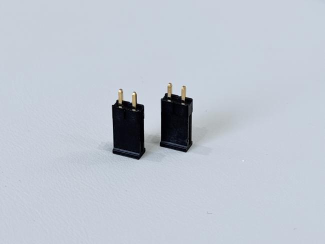
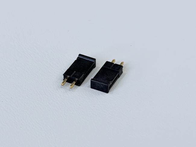
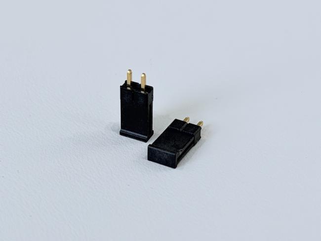
2.54mm Pitch 1×2 Single-Row Pin Header Connector, Through-Hole PCB Electronic Connector, Gold-Plated Terminals for Signal & Power Transmission
• Free samples available for quality evaluation.
• Support for both OEM & ODM customization.
• Trade Terms: EXW, FOB, CIF, CPT, etc.
This 2.54mm pitch 1×2 single-row pin header connector is designed for compact PCB applications requiring reliable electrical and electronic signal transmission. The connector features a vertical through-hole structure (8.5H), offering strong soldering retention and stable mechanical support for various PCB layouts.
Constructed with PA9T UL94-V0 high-temperature housing, the connector provides excellent heat resistance, durability, and dimensional stability during soldering processes. The terminals are made from high-conductivity Brass C2680 and plated with 50 µ” nickel and 15 µ” gold, ensuring superior conductivity, corrosion resistance, and long-term reliability.
Supporting up to 3.0A per circuit, this connector is suitable for low-power and signal interfaces in industrial, consumer, and automotive electronics.
| Product Type | Single-Row Pin Header Connector |
| Pitch | 2.54 mm |
| Pin Count | 1×2 Pins |
| Mounting Type | Vertical Through-Hole (8.5H straight type) |
| Housing Material | PA9T Black, UL94-V0 |
| Cap Material | PA9T Black, UL94-V0 |
| Terminal Material | Brass C2680 |
| Plating | Nickel ≥50 µ” (base), Gold 15 µ” (contact area) |
| Salt Spray Test | 24 Hours |
| Rated Current | 3.0A Max |
| Rated Voltage | 250V DC |
| Temperature Range | -25°C ~ +105°C |
| Contact Resistance | ≤20 mΩ Max |
| Insulation Resistance | ≥1000 MΩ Min |
| Dielectric Withstand Voltage | 500V AC / Minute |
| Environmental | HF (Halogen-Free) |
| Dimension Notes | Marked index positions are inspection reference points |
⚙️ Applications
- PCB Signal & Data Transmission: Used for board-to-board or board-to-module connections, including low-voltage signals, data transmission, and control interfaces.
- Consumer Electronics: Common in smart home appliances, printers, cameras, displays, controllers, and handheld devices for internal signal routing.
- Industrial Automation & Control Systems: Applied in PLCs, industrial control boards, sensors, meters, robotics modules, and automation I/O interfaces.
- Servers & Data Center Equipment: Used for backplane interfaces, storage modules, communication boards, and signal expansion connectors.
- Automotive Electronics: Suitable for ECUs, BMS modules, sensor units, dashboards, infotainment systems, and on-board control interfaces.
- Communication & Networking Devices: Used in routers, switches, IoT gateways, RF modules, and network communication cards.
- IoT & Smart Device Modules: Applied in Bluetooth modules, WiFi modules, GPS/Beidou modules, sensor nodes, and embedded system expansion ports.
- Power Control & Monitoring Boards: For auxiliary power transmission, monitoring signals, and low-power control circuits.
- Custom OEM/ODM Electronic Designs: Ideal for designs requiring customizable pin count, pitch, height, plating option, and configuration.
⚠️ Notes
- Ensure Correct Pin Alignment: Check orientation and positioning before mating to avoid mis-insertion, bent pins, or PCB pad damage.
- Do Not Exceed Electrical Ratings: Follow the specified current and voltage limits to prevent overheating or contact failure.
- Proper Insertion and Extraction Force: Avoid excessive force during mating/unmating to prevent deformation, cracked solder joints, or pin damage.
- Keep Contact Surfaces Clean: Ensure terminals remain free from dust, oil, oxidation, or contaminants that reduce conductivity.
- Follow Recommended Soldering Conditions: Use appropriate soldering temperature profiles according to plastic materials such as LCP, PA6T, PA66, or PBT.
- Verify PCB Hole Tolerance: Incorrect hole size may cause inadequate solder filling or mechanical instability.
- Avoid Mechanical Stress After Assembly: Do not apply lateral pressure or bending forces, especially for SMT pin headers.
- Maintain Proper Storage Conditions: Store in a dry, dust-free environment to prevent terminal oxidation; use anti-static packaging if required.
- Confirm Compatibility with Female Header: Ensure matching pitch, pin count, height, and contact design to avoid mating failure.
- Choose Correct Plating Specification: Select proper plating (gold, tin, nickel) based on your application’s durability, corrosion resistance, and signal reliability needs.


Get in Touch
Have questions about our products or want to discuss a custom order? Our team is ready to help you.