
100G QSFP28 SWDM4 Optical Transceiver 940nm Duplex LC Connector DOM MMF
100G QSFP28 SWDM4 Optical Transceiver
The 100G QSFP28 SWDM4 transceiver modules are designed for use in 100G Ethernet links over duplex multimode fiber. Four channels/lanes in the 850-940nm region @ 25.78Gbps to transport the Ethernet signal. Digital diagnostics functions are available via an I2C interface, as specified by the QSFP28 MSA
- Compliant with QSFP28 MSA
- Compliant with SWDM MSA
- Compliant with IEEE802.3bm CAUI-4
- Hot-pluggable QSFP28 form factor
- 4x25Gb/s 850mm VCSEL-based transmitter
- Supports 103.1Gbps aggregate bit rate
- Power dissipation<3.5W
- Maximum link length of 150m on OM5 multimode Fiber
- Case temperature range of 0°C to 70°C
- Duplex LC receptacles
- CAUI-4 electrical interface
- RoHS compliant
Application
- 100G Ethernet over Duplex MMF
Optical Charactristics
| Transmitter Parameter | Lane | Min | Typical | Max | Unit | Note |
| Signaling rate, each lane | 25.78125±100ppm | Gb/s | ||||
|
Lane Wavelength Range |
Lane0 Lane1 Lane2 Lane3 |
844 874 904 934 |
858 888 918 948 |
nm |
||
| Modulation Format | NRZ | |||||
| Difference in launch power between any two lanes | 4.5 | dBm | ||||
| RMS Spectral width | 0.59 | nm | 1 | |||
| Optical Modulation Amplitude (OMA), each lane | -5.5 | 3 | dBm | 2 | ||
| Average Launch Power per Lane @ TX Off State | -30 | dBm | ||||
|
Launch Power in OMA minus TDEC |
Lane0 Lane1 Lane2 Lane3 |
-7 -7 -7.4 -7.7 |
dBm |
|||
|
Transmitter and Dispersion Eye Closure |
Lane0 Lane1 Lane2 Lane3 |
4 4 4.4 4.8 |
dB |
3 |
||
| Extinction Ratio | 2 | dB | ||||
| Optical Return Loss Tolerance | 12 | dB | ||||
| Encircled Flux |
≥86% at 19 um ≤30% at 4.5 um |
4 | ||||
|
Transmitter eye mask definition {X1, X2, X3, Y1, Y2 Y3} Hit ratio 1.5x10⁻³ hits per sample |
{0.3,0.38,0.45,0.35,0.41,0.5} |
|||||
|
Notes: 1. RMS spectral width is the standard deviation of the spectrum. 2. The normative lowest value of OMA for a compliant transmitter is ‘Launch power in OMA minus TDEC, each lane (min)’ plus the actual value of ‘TDEC’, but with a value of at least ‘OMA, each lane (min)’. 3. TDEC is calculated from the measured TDECm using the methods in 3.6. TDECm is measured following the method in IEEE 802.3 clause 95.8.5 using a 12.6 GHz bandwidth reference receiver for all lanes. 4. If measured into type A1a.2 or type A1a.3 50 um fiber in accordance with IEC 61280-1-4. |
||||||
| Receiver Parameter | Lane | Min | Typical | Max | Unit | Note |
| Signaling rate, each lane | 25.78125±100ppm | Gb/s | ||||
|
Lane Wavelength Range |
Lane0 Lane1 Lane2 Lane3 |
844 874 904 934 |
858 888 918 948 |
nm |
||
| Modulation Format | NRZ | |||||
| Damage Threshold | 4.4 | dBm | ||||
|
Average Receive Power, each lane |
Lane0 Lane1 Lane2 Lane3 |
-9.5 -9.4 -9.4 -9.4 |
3.4 |
dBm |
||
| Receiver Power, each lane (OMA) | 3 | dBm | ||||
| Receiver Reflectance | -12 | dB | ||||
|
unStressed Receiver Sensitivity(OMA) |
Lane0 Lane1 Lane2 Lane3 |
-8.2 -8.4 -8.6 -8.8 |
dBm |
1 |
||
| RX_Los_Assert | -30 | dBm | ||||
| RX_Los_De-ASSERT | -12 | dBm | ||||
| RX_Los_Hysteresis | 0.5 | dBm | ||||
|
1.unstressed sensitivity at BER of 5E-5(pre FEC) |
||||||
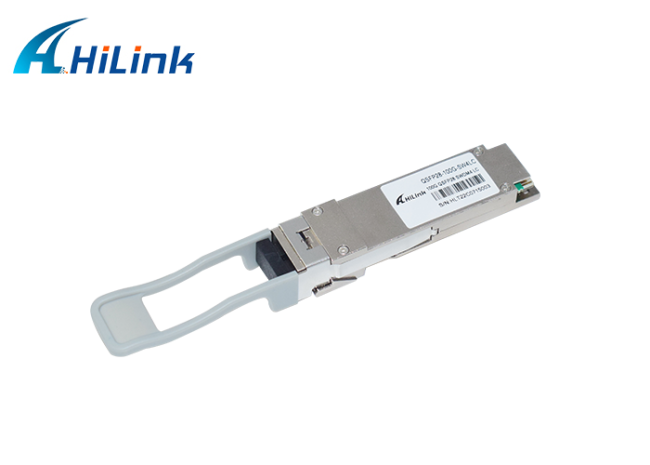
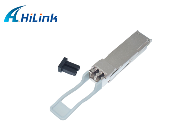
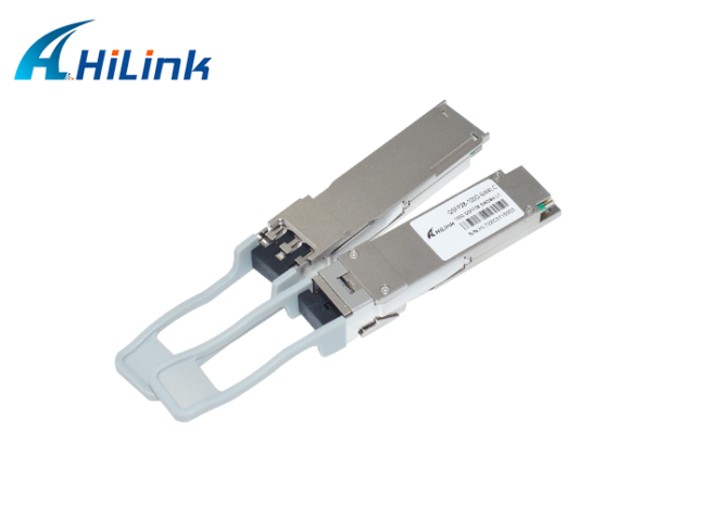
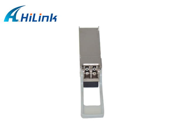
Pictures
Package & Shipping
International Express: DHL, FedEx,EMS,TNT, UPS and so on. It takes 3-7 days.
Our Service
OEM/ODM order is available
We promise all the advertised optical modules are brand new and absolutely never use old and refurbished materials. All the optical modules have been through functional test and aging test. We provide 3 years warranty for all the optical transceivers from the date of shipment.
Get in Touch
Have questions about our products or want to discuss a custom order? Our team is ready to help you.