
Industrial NEW Yaskawa ELECTRIC AC Servo Motor, 2900W 18.6 N-m 400V 11.9A SGMGH-30DCA6C
Industrial NEW Yaskawa ELECTRIC AC Servo Motor, 2900W 18.6 N-m 400V 11.9A SGMGH-30DCA6C
OTHER SUPERIOR PRODUCTS
| Yasakawa Motor, Driver SG- | Mitsubishi Motor HC-,HA- |
| Westinghouse Modules 1C-,5X- | Emerson VE-,KJ- |
| Honeywell TC-,TK- | GE Modules IC - |
| Fanuc motor A0- | Yokogawa transmitter EJA- |
| SGMGH-03ACB61 |
| SGMGH-03ACB6C |
| SGMGH-05A2A2B |
| SGMGH-05A2A61 |
| SGMGH-05A2ASC61 |
| SGMGH-05ACA61 +SGDM-05ADA |
| SGMGH-05ACA6C |
| SGMGH-05ACC21 |
| SGMGH-09A2A21 |
| SGMGH-09ACA21 |
| SGMGH-09ACA2B |
| SGMGH-09ACA2C |
| SGMGH-09ACA61 |
| SGMGH-09ACA6B |
| SGMGH-09ACA6C |
| SGMGH-09ACB61 |
| SGMGH-09ACB6B |
| SGMGH-09PCA-AM14 |
| SGMGH-12A2B2 |
| SGMGH-12A2B21 |
| SGMGH-13A2A-YR13 |
| SGMGH-13A2A-YR23 |
| SGMGH-13A2A-YR23A |
| SGMGH-13A2A-YR24 |
| SGMGH-13ACA |
| SGMGH-13ACA21 |
| SGMGH-13ACA61 |
| SGMGH-13ACA6C |
| SGMGH-13DCA61 |
| SGMGH-1AACA61 |
| SGMGH-1EACA61 |
| SGMGH-20A2B2C |
| SGMGH-20ABA6C |
| SGMGH-20ACA61 |
| SGMGH-20ACA6B |
| SGMGH-20ACA6C |
| SGMGH-20ACB2C |
| SGMGH-20ACB61 |
| SGMGH-20D2A21 |
This is where the gear system inside a servomechanism comes into the picture. The gear mechanism will take high input speed of the motor (fast) and at the output, we will get an output speed which is slower than original input speed but more practical and widely applicable. Say at initial position of servo motor shaft, the position of the potentiometer knob is such that there is no electrical signal generated at the output port of the potentiometer. This output port of the potentiometer is connected with one of the input terminals of the error detector amplifier. Now an electrical signal is given to another input terminal of the error detector amplifier. Now difference between these two signals, one comes from potentiometer and another comes from external source, will be amplified in the error detector amplifier and feeds the DC motor.
This amplified error signal acts as the input power of the DC motor and the motor starts rotating in desired direction. As the motor shaft progresses the potentiometer knob also rotates as it is coupled with motor shaft with help of gear arrangement. As the position of the potentiometer knob changes there will be an electrical signal produced at the potentiometer port. As the angular position of the potentiometer knob progresses the output or feedback signal increases. After desired angular position of motor shaft the potentiometer knob is reaches at such position the electrical signal generated in the potentiometer becomes same as of external electrical signal given to amplifier. At this condition, there will be no output signal from the amplifier to the motor input as there is no difference between external applied signal and the signal generated at potentiometer. As the input signal to the motor is nil at that position, the motor stops rotating. This is how a simple conceptual servo motor works.
0.85 to 15 kW servomotors require servomotor-end connector and brake power supply connector. The servomotor-end connector is the same as is used for servomotors without holding brakes.
To order a brake power supply connecter kit (0.85 to 15 kW) with the order no. below, contact your Yaskawa representative. Connector Type S: Straight plug A: L-shaped plug Bush Size*1 S : Size S (4.0 dia. to 6.0 dia.) M : Size M (6.0 dia. to 9.0 dia.) L : Size L (9.0 dia. to 11.6 dia.) Contact Pin Size S2: Soldered C3: Crimped type*2 *1: A size-M connector kit is available as a standard equipment. *2: A crimp tool (model: 357J-50448T) by DDK Ltd. is required.
(2) Servomotor: A main actuator that moves a controlled system. Two types aravailable: AC servomotor and DC servomotor.
(3) Detector: A position or speed detector. Normally, an encoder mounted ona motor is used as a position detector.
(4) Servo amplifier: An amplifier that processes an error signal to correct the difference between a reference and feedback data and operates theservomotor accordingly. A servo amplifier consists of a
comparator, which processes error signals, and a power amplifier,which operates the servomotor.
(5) Host controller: A device that controls a servo amplifier by specifying a positionor speed as a set point.
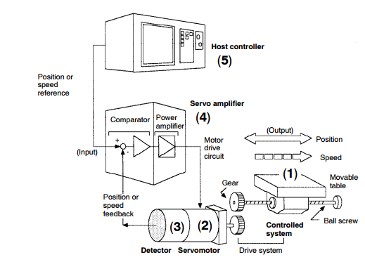
(1) Controlled system
In the previous figure, the controlled system is a movable table for which the positionor speed is controlled. The movable table is driven by a ball screw and is connected tothe servomotor via gears.
So, the drive system consists of:
Gears + Ball Screw
This drive system is most commonly used because the power transmission ratio(gear ratio) can be freely set to ensure high positioning accuracy. However, play in thegears must be minimized.
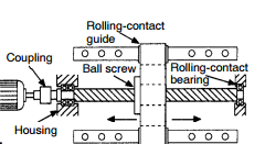
table:
When the power transmission ratio is 1 :1, a coupling is useful because it has noplay.
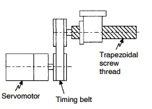
A trapezoidal screw thread does not proviexcellent positioning accuracy, so can be treated as a minor coupling device.
Get in Touch
Have questions about our products or want to discuss a custom order? Our team is ready to help you.