
11KV Resin Cast Split Core Current Transformer , Low Voltage Current Transformer Outdoor
Resin 11KV Split Core Current Transformer Outdoor High Quality
Introduction
LZCK series split core current transformer is suitable forcurrent measurement and microcomputer protection of electrical equipment in 10KV and 35KV AC power system.
It is widely used in compact fully insulated ring network switchgears such as ABB-Safe Ring/Safe Plus...and cable distribution boxes.
The transformer can be directly installed at the inlet and outlet cables. The slice is imported silicon material. Thesemicircular ring core and secondary windings arevacuum poured by insulated resin.
Features
The current transformer with high strength PVC shell, all cast bus structure. Transformer directly stuck in the cable Three rubber rings to resist the cable and cable with one. Transformer core using high-quality silicon steel roll, the second wire wound evenly on the core. Transformer open structure can not cut off the cable installation
PARAMETERS
| Technical parameters | |
|---|---|
| Standards | IEC60044-1; IEC 61869-2; NTC 2205; GB1208-2006; ANSI C57.13 |
| Accuracy Class | 0.5S, 0.5%, 1%, 3% |
| Range of primary rated current | 100-1500A |
| Range of Rated load | ≤10VA |
| Rated frequency | 50/60Hz |
| Rated secondary current | 5A or 1A |
| Rated short-time thermal current | 40kA, 1S |
| Rated continuous thermal current | 150%I1n |
| Secondary winding power frequency withstand voltage | 3kV, 1min |
| Safety Factor Rating | (FS) <10 |
| Output signal | 1A, 5A, 333mV, 1V or 5V(customized) |
| Cable length | 2.5m, 5m, 10m(customized) |
| Flame retardant ABS plastic shell inside, jaw waterproof apron. | |
| Mechanical parameters | |
| Aperture (mm) | Φ55 |
| Dimensions (W×D×H) (mm) | 180×138×52 |
| Weight (kg) | 2 |
| Working conditions | |
| Operating temperature | -35°C to +65°C, not exceeding +40°C |
| Storage temperature | -40°C to +70°C |
| Ingress Protection | IP65 |
| Environment | outdoors or indoors |
| The Height of above sea level | 0- 3000m |
| Conditions | No existence of severely begrimed, erosive and radioactive gas in the air. Continuous working under the rated current is allowed. |
SELECTION GUIDE
| Technical parameters | |
|---|---|
| Standards | IEC60044-1; IEC 61869-2; ANSI C57.13; NTC 2205; GB1208-2006 |
| Rated primary current | 30-600A |
| Rated load | ≤10VA |
| Rated frequency | 50Hz or 60Hz |
| Rated secondary current | 5A or 1A |
| Rated short-time thermal current | 40kA, 1S |
| Rated continuous thermal current | 120%I1n |
| Secondary winding power-frequency voltage | 3kV, 1min |
| Instrument security factor | FS≤10 |
| Mechanical parameters | |
| Dimensions (W×D×H) (mm) | φ50xφ110x52 |
| Weight (kg) | 1.6 |
| Operating conditions | |
| Operating temperature | -35°C to +55°C |
| Daily average temp | <+40°C |
| Altitude | <3500 meters |
| Condition | No existence of severely begrimed, erosive and radioactive gas in the air. Permission of long-term operation under rated current. |
TECHNICAL DATA
| Type | LZCK322-10 | LZCK322-10 | ||||
|---|---|---|---|---|---|---|
| Purpose | Measuring current transformer | Protection current transformer | ||||
| Ratio | Accuracy class and rated load(VA) | Accuracy class and rated load(VA) | ||||
| I1/I2 | 0.5 | 1 | 3 | 10P15 | 10P10 | 10P5 |
| 30/1 | 1 | 1.5 | ||||
| 50/1 | 1 | 2 | 1.25 | |||
| 75/1 | 1.5 | 2.5 | 1 | 2 | ||
| 100/1 | 2 | 2.5 | 3 | 1.5 | 2.5 | |
| 200/1 | 2.5 | 1.25 | 2.5 | |||
| 300/1 | 3.75 | 1.25 | 2.5 | |||
| 400/1 | 7.5 | 1.25 | 2.5 | |||
| 500/1 | 10 | 1.25 | 3 | |||
| 600/1 | 10 | 1.5 | 3 | |||
| 50/5 | 2.5 | |||||
| 75/5 | 2.5 | |||||
| 100/5 | 2.5 | |||||
| 200/5 | 3.75 | |||||
| 300/5 | 5 | |||||
| 400/5 | 7.5 | 2.5 | ||||
| 500/5 | 7.5 | 2.5 | ||||
| 600/5 | 10 | 3.75 | ||||
SELECTION GUIDE
| Model | Primary rated current | Rated load | Aperture (mm) | Description (mm) | Weight (kg) | Material | Water-proof |
|---|---|---|---|---|---|---|---|
| LZCK-55 | 100-1500A | ≤10VA | φ55 | 180×138×52 | 2 | PC | IP65 |
| LMCK185-10 | 300-3000A | ≤25VA | φ185 | 350×283×55 | 4.5 | PC | IP65 |
| LZCK310-10 | 300-600A | ≤10VA | φ50 | φ50 x φ110 x 32 | 1 | Resin | silicon case (option) |
| LZCK322-10 | 30-600A | ≤10VA | φ50 | φ50 x φ110 x 52 | 1.6 | Resin | silicon case (option) |
| LZCK350-10 | 20-600A | ≤25VA | φ50 | φ50 x φ110 x 105 | 3.1 | Resin | silicon case (option) |
| LZCG530-10 | 30-600A | ≤20VA | φ45 | φ45 x φ120 x 65 | 2.1 | Resin | silicon case (option) |
Wiring diagrams
P1, P2 is primary polarity terminal, S1, S2 is secondary polarity terminal.
P2, S2 is homonymous terminals (subtractive polarity).
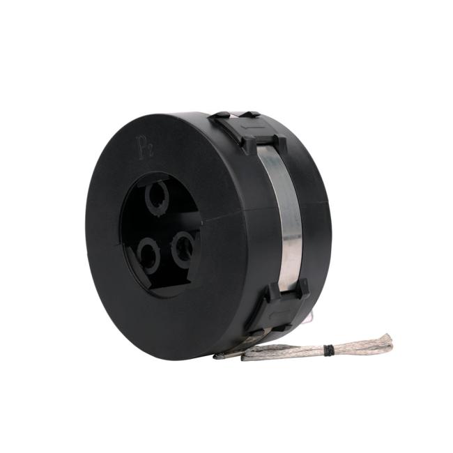
Product picture
Get in Touch
Have questions about our products or want to discuss a custom order? Our team is ready to help you.