
Jf800 Gunmetal Bronze Bimetal Bearing Bushes Groove Design
JF800 Gunmetal Bronze Bimetal Bearing Bushes with Groove Design refer to bushings made of a bimetallic material combining gunmetal (a type of bronze alloy) and another metal, typically steel. The groove design is a specific feature that allows for lubrication or the retention of lubricant, enhancing the bushing's performance and durability.
Gunmetal bronze is chosen for its excellent wear resistance, corrosion resistance, and load-bearing capacity. The bimetallic construction provides a strong and durable backing material, while the gunmetal layer ensures smooth operation and reduced friction.
These bushings are widely used in various industrial applications where high-performance and long-lasting bearings are required. The groove design makes them particularly suitable for applications where lubrication is critical, such as in rotating machinery, engines, and pumps. The use of JF800 Gunmetal Bronze Bimetal Bearing Bushes with Groove Design can significantly improve the efficiency and reliability of mechanical systems.
Jf800 Gunmetal & Bronze Bush Groove Bushing can be produced from an ID of 3mm all the way up to 400mm.
Gunmetal bushes and Gunmetal Bushings bronze bushes INCH SIZE BEARINGS
Wholesale Customized Oil Groove Brass Shaft Bushing
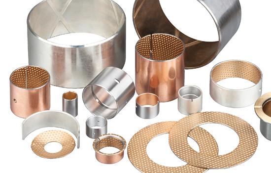
Bimetal Bearings Bushings,Oil Hole Design, Bimetal Cylindrical Bushings, Flange Bearings, Thrust Washer made to order from china. Material (CuPb10Sn10, SAE-797, JIS-LBC3 Bronze Alloy )
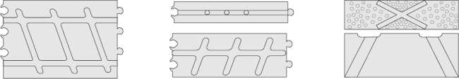
Types of Oil Prockets for bimetal bushings
Oil Holes Form
Diamond Form
Smooth ,No Oil Pocket
| Oil Hole is necessary to design if bimetal bushings have lubricated sufficiently; the following oil hole design is recommended, which is also suitable for bimetal series without special requirements. | |||||
| Bushing O.D. (D) | Φ14>D ≤ 22 | Φ22>D ≤ 40 | Φ40>D ≤ 50 | Φ50>D ≤ 100 | Φ100>D ≤ 180 |
| Oil Hole Diameter (mm) | 3 | 4 | 5 | 6 | 7 |
| Bimetal Bearings Oil hole location should keep away from the split gap & loading area, and in favor of oil-taking. | |||||
Manufacturer of Self Lubricating Bushing - Self Lubricating Graphite Bush, Self Lubricating Bimetal Bushings
Bimetallic Material Characteristics
Material (CuPb10Sn10, SAE-797, JIS-LBC3 Bronze Alloy ) CuSn10Pb10 CC495K
| Chemical composition mass /% | |||||||||
|---|---|---|---|---|---|---|---|---|---|
| Cu | Sn | Al | Fe | Mn | Ni | Pb | Si | P | Zn |
| 78.0-82.0 | 9.0-11.0 | 0.01 | 0.25 | 0.2 | 2 | 8.0-11.0 | 0.01 | 0.1 | 2 |
We can produce precise finished parts according to customers' special requirements and drawings.
Sintered SAE797 Layer + Steel Backing + Copper Plating / Tin-Plating
JF800 bimetal bearings are steel and copper alloy products with low carbon steel plate as the matrix material and sintered CuPb10Sn10 or CuSn6Zn6Pb3 on the surface. The bimetlal t is a double alloy bearing bearing capacity of the strongest one, heavy vehicle balance bridge bushing, gasket; The slave wheel of a bulldozer; Automotive steel bushing, all used in this product. It is a widely used high - load low - speed sliding bearing.

Bimetal Bearing Design
We can design bimetal bearings according to the operating conditions of copper alloy surface processing of various types of oil tank, oil hole, hole, etc., in order to suit to cannot continue to go hard or go occasion. Good bonding strength and optimum bearing capacity can be obtained by secondary sintering and secondary extrusion.
Types of Oil Grooves for bimetal bushings
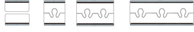
Types of Butt Jionts for bimetal bushings (Slit & Clinch) Bimetal Bearings Bushings Buckle Form
Technical Data Of Graphite Bushing Bearings
| Maximum dynamic load | 140P N/mm² | MAX Temperature°C | Grease lubrication | 150°C | |
| Maximum linear velocity | Grease lubrication | 2.5Vm/s | Fluid lubrication | 250°C | |
| MAX PV | 2.8N/mm². m/s | Match the diameter of axle | HRC | ≥ 53 | |
| μ | 0.05~0.15 | Ra | 0.16~0.63 | ||
| Maximum linear velocity | Fluid lubrication | 10 | Alloy layer hardness | 80~120 | |
| MAX PV | 10 | Coefficient of thermal conductivity | 47W/mk | ||
| μ | 0.04~0.12 | Linear expansion coefficient (axial) | 18×10-6/K | ||
Thickness Tolerance Between Inner Hole Machining And Non-Machining For Bimetal Bearings
Norminal Thiickness |
Tolerances of Series B (non-machinable) |
Tolerances of Series C (non-machinable) |
| 1.0 | -0.025 | +0.25 +0.15 |
| 2.0 | -0.030 | +0.25 +0.15 |
| 2.5 | -0.035 | +0.25 +0.15 |
| 3.0 | -0.040 | +0.30 +0.15 |
| 3.5 | -0.045 | +0.30 +0.15 |
| 3.5 | -0.050 | +0.30 +0.15 |
Standard Tolerance Dimension Table
|
d
|
D
|
相配轴径
公差( h8)
|
相配座孔
公差(H7)
|
压入H7座孔
内径公差
|
Wall thickness
壁厚
|
注油孔
|
f1
|
f2
|
L 0
-0.40 |
||||||||
|
min
|
max
|
10
|
15
|
20
|
25
|
30
|
40
|
50
|
60
|
||||||||
|
10
|
12
|
10-0.022
|
12+0.018
|
+0.148
+0.010 |
0.995
|
0.935
|
4
|
0.5
|
0.3
|
1010
|
1015
|
1020
|
|
|
|
|
|
|
12
|
14
|
12-0.027
|
14+0.018
|
1210
|
1215
|
1220
|
|
|
|
|
|
||||||
|
14
|
16
|
14-0.027
|
16+0.018
|
1410
|
1415
|
1420
|
|
|
|
|
|
||||||
|
15
|
17
|
15-0.027
|
17+0.018
|
1510
|
1515
|
1520
|
|
|
|
|
|
||||||
|
16
|
18
|
16-0.027
|
18+0.018
|
0.8
|
0.4
|
1610
|
1615
|
1620
|
|
|
|
|
|
||||
|
18
|
20
|
18-0.027
|
20+0.021
|
+0.151
+0.010 |
1810
|
1815
|
1820
|
1820
|
|
|
|
|
|||||
|
20
|
23
|
20-0.033
|
23+0.021
|
+0.181
+0.020 |
1.490
|
1.430
|
2010
|
2015
|
2020
|
2020
|
|
|
|
|
|||
|
22
|
25
|
22-0.033
|
25+0.021
|
6
|
2210
|
2215
|
2220
|
2220
|
|
|
|
|
|||||
|
24
|
27
|
24-0.033
|
27+0.021
|
1.0
|
0.5
|
2410
|
2415
|
2420
|
2420
|
2430
|
|
|
|
||||
|
25
|
28
|
25-0.033
|
28+0.021
|
|
2515
|
2520
|
2520
|
2530
|
|
|
|
||||||
|
26
|
30
|
26-0.033
|
30+0.021
|
+0.205
+0.030 |
1.980
|
1.920
|
|
2615
|
2620
|
2620
|
2630
|
|
|
|
|||
|
28
|
32
|
28-0.033
|
32+0.025
|
|
2815
|
2820
|
2820
|
2830
|
2840
|
|
|
||||||
|
30
|
34
|
30-0.033
|
34+0.025
|
1.2
|
0.6
|
|
3015
|
3020
|
3020
|
3030
|
3040
|
|
|
||||
|
32
|
36
|
32-0.039
|
36+0.025
|
|
3215
|
3220
|
3220
|
3230
|
3240
|
|
|
||||||
|
35
|
39
|
35-0.039
|
39+0.025
|
|
|
3520
|
3520
|
3530
|
3540
|
3550
|
|
||||||
|
38
|
42
|
38-0.039
|
42+0.025
|
8
|
|
|
3820
|
3820
|
3830
|
3840
|
3850
|
|
|||||
|
40
|
44
|
40-0.039
|
44+0.025
|
|
|
4020
|
4020
|
4030
|
4040
|
4050
|
|
||||||
|
d
|
D
|
相配轴径公差(h8)
|
相配座孔公差(H7)
|
压入H7座孔内径公差
|
Wall thickness
壁厚
|
注油孔
|
f1
|
f2
|
L 0
-0.40 |
||||||||
|
min
|
max
|
25
|
30
|
40
|
50
|
60
|
80
|
90
|
100
|
||||||||
|
45
|
50
|
45-0.039
|
50+0.025
|
+0.205
+0.030 |
2.460
|
2.400 |
8
|
1.5
|
1.0
|
4525
|
4530
|
4540
|
4550
|
|
|
|
|
|
50
|
55
|
50-0.039
|
55+0.030
|
+0.210
+0.030 |
|
5030
|
5040
|
5050
|
5060
|
|
|
|
|||||
|
55
|
60
|
55-0.046
|
60+0.030
|
|
5530
|
5540
|
5550
|
5560
|
|
|
|
||||||
|
60
|
65
|
60-0.046
|
65+0.030
|
|
6030
|
6040
|
6050
|
6060
|
|
|
|
||||||
|
65
|
70
|
65-0.046
|
70+0.030
|
|
6530
|
6540
|
6550
|
6560
|
|
|
|
||||||
|
70
|
75
|
70-0.046
|
75+0.030
|
|
7030
|
7040
|
7050
|
7060
|
7080
|
|
|
||||||
|
75
|
80
|
75-0.046
|
80+0.030
|
9.5
|
|
7530
|
7540
|
7550
|
7560
|
|
|
|
|||||
|
80
|
85
|
80-0.046
|
85+0.035
|
+0.215
+0.030 |
|
|
8040
|
8050
|
8060
|
8080
|
|
|
|||||
|
85
|
90
|
85-0.054
|
90+0.035
|
|
8530
|
|
8550
|
8560
|
8580
|
|
85100
|
||||||
|
90
|
95
|
90-0.054
|
95+0.035
|
|
|
|
9050
|
9060
|
9080
|
|
90100
|
||||||
|
95
|
100
|
95-0.054
|
100+0.035
|
|
|
|
|
9060
|
9080
|
9090
|
90100
|
||||||
|
100
|
105
|
100-0.054
|
105+0.035
|
|
|
|
|
10060
|
10080
|
10090
|
100100
|
||||||
|
105
|
110
|
105-0.054
|
110+0.035
|
|
|
|
|
10560
|
10580
|
|
105100
|
||||||
|
110
|
115
|
110-0.054
|
115+0.035
|
|
|
|
|
11060
|
11080
|
|
110100
|
||||||
|
115
|
120
|
115-0.054
|
120+0.035
|
|
|
|
11550
|
|
11580
|
|
|
||||||
|
120
|
125
|
120-0.054
|
125+0.040
|
+0.220
+0.030 |
|
|
|
12050
|
12060
|
|
|
120100
|
|||||
|
125
|
130
|
125-0.063
|
130+0.040
|
|
|
|
|
|
|
|
125100
|
||||||
|
130
|
135
|
130-0.063
|
135+0.040
|
|
|
|
|
13060
|
|
|
130100
|
||||||
|
135
|
140
|
135-0.063
|
140+0.040
|
|
|
|
|
13560
|
13580
|
|
|
||||||
|
140
|
145
|
140-0.063
|
145+0.040
|
|
|
|
|
14060
|
14080
|
|
140100
|
||||||
|
150
|
155
|
150-0.063
|
155+0.040
|
|
|
|
|
15060
|
15080
|
|
150100
|
||||||
We can solve bimetal bushings bearings solutions for you.
Bi-metallic bushing is formed from steel strips with alloy lining material. The alloy lined surface can be machined oil grooves, holes, formed Indentations etc according to different application. It is suitable for high load, lower speed oscillation & rotation movement.

Get in Touch
Have questions about our products or want to discuss a custom order? Our team is ready to help you.