
Sysolution D60-12A Receiving Card 12 HUB75E Ports 512x384 Pixels LED Display Controller
Sysolution Receiving card D60-12A
Product Introduction:
D60-12A is a standard receiving card launched by Sysolution Technology. It adopts 12 standard HUB75E interfaces and supports up to 24 groups of RGB parallel data. Load up to 512X256 pixels; It has strong processing capacity, super stable performance and high cost performance.
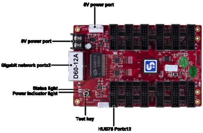
Loading capacity:
|
Three lines parallelism (RGB) |
Data interface/number | Drive |
Maximum loading (Pixels) |
Brightness correction loading (pixels) | Chromaticity correction loading (pixels) |
| 24 groups | HUB75E/12 | Normal | 512*256 | 512*256 | 256*320 |
| PWM | 512*256 | 512*256 | 256*320 |
| Number of cascade cards | Support scan line | ||
| ≤1000PCS | 1-64 Scan |
Functions & Features:
| Function | Description |
| Improved Display Effect |
|
| Improved Operability |
|
|
Improved Hardware Stability |
|
|
Intelligent Software Upgrade |
1. Support receiving card configuration parameter readback:Can read back the current receiving card configuration parameters on LedSet 4.0. 2. Support network cable bit error rate detection: On LedSet 4.0, the quality of the network cable communication signal connected to the system hardware can be monitored in real time to quickly judge the quality of the network cable and troubleshoot. 3. Communication monitoring function:Monitor the working status of the receiving card in real time on LedSet 4.0. |
Pins:
24 Parallel Data Interface Definitions
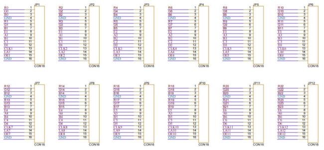
JP1——JP12 Data Interface Definition
| Instruction | Description | Pin | Pin | Description | Instruction |
|
RGB Data output |
R | 1 | 2 | G | RGB Data output |
| B | 3 | 4 | GND | Ground | |
| R | 5 | 6 | G | RGB Data output | |
| B | 7 | 8 | E | Line decoding signal | |
| Line decoding signal | A | 9 | 10 | B | |
| C | 11 | 12 | D | ||
| Shift clock output | CLK | 13 | 14 | LAT | Latch signal output |
| Display enable(remarks1) | OE | 15 | 16 | GND | ground |
Note 1: Pin 15 is the display enable pin. When PWM chip is used, it is GCLK signal.
J16 Interface definition
| Description | Pin | Pin | Description |
| +5V | 1 | 2 | GND |
| FLS_CS | 3 | 4 | FLS_DO |
| FLS_CLK | 5 | 6 | FLS_DI |
| PROGRAM_B | 7 | 8 | mCONF_DONE |
| GND | 9 | 10 | +5V |
J12 Indicator interface definition
| Pin | 1 | 2 | 3 | 4 | 5 |
| Definition | GND/KEY- | KEY+ | LEDR- | VCC/LED+ | LEDG- |
J14 Power socket definition
| Pin | 1 | 2 | 3 | 4 |
| Definition | VCC | VCC | GND | GND |
Indicator Description:
| Indicator | Location | State | Description |
|
Status indicator (green) |
U1 |
Flashes evenly and slowly |
The receiving card works normally, the network cable is connected normally, and there is no DVI signal input. |
|
Flashes evenly and quickly |
The receiving card works normally, the network cable is connected normally, and there is a DVI signal input. | ||
| Off | No Gigabit signal | ||
|
3 flashes quickly at intervals |
The receiving card works normally, the network cable circuit is in connection, and there is a DVI signal input. | ||
|
Status indicator (red) |
U3 | On | Normal power supply |
Dimension:

Working Conditions:
| Electrical Parameters | Input voltage | DC3.5-5.5V |
| Rated current | 0.6A | |
| Rated power | 3W | |
| Working environment | Working temperature | -20℃-70℃ |
| Working humidity | 10%RH-90%RH | |
| Storage environment | Working temperature | -25℃~125℃ |
| Board size | 144.02mmX91.2mm | |
| Net weight | 100.8g | |
| Certification Information | RoHS Compliant, CE-EMC Compliant | |
Get in Touch
Have questions about our products or want to discuss a custom order? Our team is ready to help you.