
A105 Forged Steel Flanged Gate Valve Pressure 1.6/2.5/4.0/6.4mpa Rising Stem Dn150
Forged Steel A105 High Pressure 1.6/2.5/4.0/6.4 Mpa Rising Stem Flanged Gate Valve
Usage
Forged steel gate valve refers to the gate valve whose pressure bearing valve body and bonnet are forged. The movement direction of the opening and closing parts of the forged steel gate valve is perpendicular to the fluid direction. The forged steel gate valve can only be fully opened and closed, and cannot be adjusted or throttled; This series of valves are mainly used in petroleum, chemical industry, power station and other industries to cut off or connect the pipeline and maintain the normal operation of the system.
working principle
Valve closing: turn the hand wheel or other driving device clockwise, and the valve rod nut drives the valve rod downward to close the valve.
Valve opening: rotate the hand wheel or other driving device counterclockwise, and the valve rod nut drives the valve rod upward to open the valve.
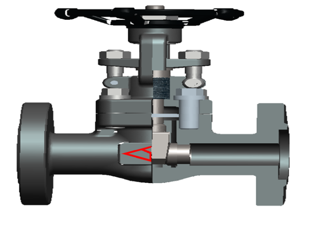
Structural features
1. the valve stem seal is realized through the double seal design of packing + upper seal.
2 the valve rod and the ram are connected in a "t" structure, which is easy to install. In addition, the head of the valve rod is designed to be spherical, so that when the valve is closed, the valve rod and the ram are in point contact, with a self centering function.
3 the valve body adopts the slot structure to realize the ram stroke guidance, and the friction between the ram and the valve seat sealing ring is reduced during the opening and closing process.
4 the valve body and bonnet shall be connected by tenon and groove surface, which can reduce the extension and overpressure deformation of metal spiral wound gasket under the preload.
5 the valve seat adopts expansion structure to ensure compact and effective fit.
6 the movable joint is connected by bolts, nuts and pins. It has the advantages of convenient installation, simple structure, strong stability and long service life.
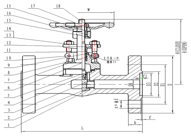
Material of main parts
| No. | Name | Material | ||||||||
| 1 | Body | A105N | A350 LF2 | A182 F11 | A182 F22 | A182 F304 | A182 F316 | A182 F304L | A182 F316L | |
| 2 | Seat | 2Cr13/STL | A182 F304/STL | A182 F316/STL | A182 F304L/STL | A182 F316L/STL | ||||
| 3 | Disc | 2Cr13/STL | A182 F304/STL | A182 F316/STL | A182 F304L/STL | A182 F316L/STL | ||||
| 4 | Stem | 1Cr13 | A276 304 | A276 316 | A276 304L | A276 316L | ||||
| 5 | gasket | 201+Flexible graphite/304+Flexible graphite | ||||||||
| 6 | Bonnet | A105N | A350 LF2 | A182 F11 | A182 F22 | A182 F304 | A182 F316 | A182 F304L | A182 F316L | |
| 7 | bolt | A193 B7 | A193 B7 | A193 B16 | A193 B16 | A193 B8 | A193 B8M | A193 B8M | A193 B8M | |
| 8 | packing | Flexible graphite | ||||||||
| 9 | packing | Steel wire packing(304+Flexible graphite) | ||||||||
| 10 | pin | 45 | ||||||||
| 11 | Packing gland | 2Cr13 | 2Cr13 | 2Cr13 | 2Cr13 | A276 304 | A276 316 | A276 304L | A276 316L | |
| 12 | Packing pressing plate | A105N | A350 LF2 | A182 F11 | A182 F22 | A182 F304 | A182 F316 | A182 F304L | A182 F316L | |
| 13 | Nut | A194 2H | A194 2H | A194 2H | A194 2H | A194 8M | A194 8M | A194 8M | A194 8M | |
| 14 | bolt | A193 B7 | A193 B7 | A193 B7 | A193 B7 | A193 B8 | A193 B8M | A193 B8M | A193 B8M | |
| 15 | shim | 65Mn | ||||||||
| 16 | Stem nut | 35/1Cr13 | ||||||||
| 17 | handwheel | malleable iron | ||||||||
| 18 | Lock nut | A194 2H | A194 8M | |||||||
Applicable medium and temperature range of shell material
| Body material | A105N | A350 LF2 | A182 F11/F22 | A182 F304/F316 | A182 F304L | A182 F316L |
| suitable tempresture(℃) | -29~425 | -46~345 | -29~538 | -29~538 | -29~425 | -29~450 |
| medium | Water, steam, oil, etc | Low temperature, water, steam, oil products, natural gas, etc | Water, steam, oil products, natural gas, etc | Water, steam, oil products, natural gas, etc | ||
Note: when the medium is flammable and explosive, the working temperature of the pipeline system must be limited.
Main connection dimensions and overall dimensions
| DN15 ~DN50,PN16 Main connection dimensions and Boundary dimensions of forged steel flange gate valve | ||||||||||
| DN | L | D | D1 | D2 | b | f | n-φd | H(CLOSE) | H(OPEN) | W |
| 15 | 130 | 95 | 65 | 45 | 16 | 2 | 4-14 | 142 | 158 | 100 |
| 20 | 150 | 105 | 75 | 58 | 18 | 2 | 4-14 | 144 | 159.5 | 100 |
| 25 | 160 | 115 | 85 | 68 | 18 | 2 | 4-14 | 170 | 191 | 120 |
| 32 | 180 | 140 | 100 | 78 | 18 | 2 | 4-18 | 199 | 255.5 | 160 |
| 40 | 200 | 150 | 110 | 88 | 18 | 2 | 4-18 | 214 | 248 | 160 |
| 50 | 250 | 165 | 125 | 102 | 18 | 2 | 4-18 | 244.5 | 286.5 | 180 |
| DN15 ~DN50,PN25 Main connection dimensions and Boundary dimensions of forged steel flange gate valve | ||||||||||
| NPS | L | D | D1 | D2 | b | f | n-φd | H(CLOSE) | H(OPEN) | W |
| 1/2 | 130 | 95 | 65 | 45 | 16 | 2 | 4-14 | 142 | 158 | 100 |
| 3/4 | 150 | 105 | 75 | 58 | 18 | 2 | 4-14 | 144 | 159.5 | 100 |
| 1 | 160 | 115 | 85 | 68 | 18 | 2 | 4-14 | 170 | 191 | 120 |
| 1-1/4 | 180 | 140 | 100 | 78 | 18 | 2 | 4-18 | 199 | 255.5 | 160 |
| 1-1/2 | 200 | 150 | 110 | 88 | 18 | 2 | 4-18 | 214 | 248 | 160 |
| 2 | 250 | 165 | 125 | 102 | 20 | 2 | 4-18 | 244.5 | 286.5 | 180 |
| DN15 ~DN50,PN40 Main connection dimensions and Boundary dimensions of forged steel flange gate valve | ||||||||||||
| NPS | L | D | D1 | D2 | D3 | b | f | f1 | n-φd | H(CLOSE) | H(OPEN) | W |
| 1/2 | 130 | 95 | 65 | 45 | 40 | 16 | 2 | 4 | 4-14 | 142 | 158 | 100 |
| 3/4 | 150 | 105 | 75 | 58 | 51 | 18 | 2 | 4 | 4-14 | 144 | 159.5 | 100 |
| 1 | 160 | 115 | 85 | 68 | 58 | 18 | 2 | 4 | 4-14 | 170 | 191 | 120 |
| 1-1/4 | 180 | 140 | 100 | 78 | 66 | 18 | 2 | 4 | 4-18 | 199 | 255.5 | 160 |
| 1-1/2 | 200 | 150 | 110 | 88 | 76 | 18 | 3 | 4 | 4-18 | 214 | 248 | 160 |
| 2 | 250 | 165 | 125 | 102 | 88 | 20 | 3 | 4 | 4-18 | 244.5 | 286.5 | 180 |
| DN15 ~DN50,PN63 Main connection dimensions and Boundary dimensions of forged steel flange gate valve | ||||||||||||
| NPS | L | D | D1 | D2 | D3 | b | f | f1 | n-φd | H(CLOSE) | H(OPEN) | W |
| 1/2 | 170 | 105 | 75 | 45 | 40 | 20 | 2 | 4 | 4-14 | 142 | 158 | 100 |
| 3/4 | 190 | 130 | 90 | 58 | 51 | 22 | 2 | 4 | 4-18 | 144 | 159.5 | 100 |
| 1 | 210 | 140 | 100 | 68 | 58 | 24 | 2 | 4 | 4-18 | 170 | 191 | 120 |
| 1-1/4 | 230 | 155 | 110 | 78 | 66 | 26 | 2 | 4 | 4-22 | 199 | 255.5 | 160 |
| 1-1/2 | 240 | 170 | 125 | 88 | 76 | 28 | 3 | 4 | 4-22 | 214 | 248 | 160 |
| 2 | 250 | 180 | 135 | 102 | 88 | 26 | 3 | 4 | 4-22 | 244.5 | 286.5 | 180 |
| DN15 ~DN50,PN100 Main connection dimensions and Boundary dimensions of forged steel flange gate valve | ||||||||||||
| NPS | L | D | D1 | D2 | D3 | b | f | f1 | n-φd | H(CLOSE) | H(OPEN) | W |
| 1/2 | 170 | 105 | 75 | 45 | 40 | 20 | 2 | 4 | 4-14 | 142 | 158 | 100 |
| 3/4 | 190 | 130 | 90 | 58 | 51 | 22 | 2 | 4 | 4-18 | 144 | 159.5 | 100 |
| 1 | 210 | 140 | 100 | 68 | 58 | 24 | 2 | 4 | 4-18 | 170 | 191 | 120 |
| 1-1/4 | 230 | 155 | 110 | 78 | 66 | 26 | 2 | 4 | 4-22 | 199 | 255.5 | 160 |
| 1-1/2 | 240 | 170 | 125 | 88 | 76 | 28 | 3 | 4 | 4-22 | 214 | 248 | 160 |
| 2 | 250 | 195 | 145 | 102 | 88 | 30 | 3 | 4 | 4-26 | 244.5 | 286.5 | 180 |
Get in Touch
Have questions about our products or want to discuss a custom order? Our team is ready to help you.