
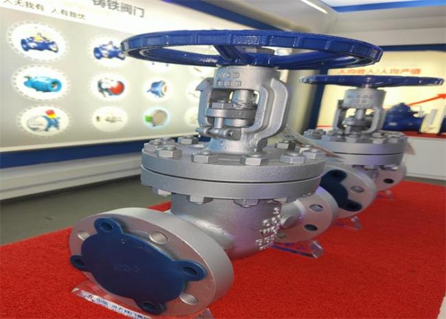
Api 150lb Pressure Flange Water Oil Gate Valve Dn50 Dn125 Dn600
API Cast Steel Rinsing Stem 150LB Pressure DN50-DN600 Flanged Gate Valve
Structure and principle of action
1. the valve is flange connected;
2. the valve is composed of valve body, bonnet, gate, valve rod, hand wheel and other parts. By rotating the hand wheel, the
The valve rod rises or falls, thus driving the ram to rise or fall, making a linear displacement perpendicular to the fluid,
To achieve the purpose of opening and closing.
Valve features
① It is allowed to remove the hand wheel when the valve is in the full open position;
② The filler can be replaced with different materials and structures according to customer needs;
③ The middle gasket adopts metal corrugated gasket, which has better sealing performance and longer service life, and can be disassembled and used repeatedly;
④ The integral guide rail inside the valve body can ensure that the ram remains centered at any position when opening and closing
⑤ The connection strength between the valve rod and the ram exceeds the strength of the valve rod thread;
⑥ The anti blow out valve rod is designed with a conical upper sealing surface, which is close to the valve cover when the valve is fully opened;
⑦ The elastic wedge gate can compensate the surface distortion of the seat ring and the deformation of the valve body caused by pipeline stress;
The valve seat ring is installed by seal welding, which can weld sealing surfaces of different materials according to customer requirements.
Precautions in storage, installation and use
1. the valve shall be stored in a dry warehouse and shall not be stored in the open air.
2. for long-term storage, it should be maintained regularly.
3. the valve can be installed on any pipeline.
4. pressure test shall be carried out before installation, and installation can be carried out only after it meets the requirements.
5. clean the pipe and valve cavity before installation.
6. the hand wheel shall not be used for lifting.
7. the product shall not be subjected to large external force after installation.
8. the operating conditions shall be consistent with the requirements in the performance specification.
9. turn the hand wheel clockwise to close, and vice versa to open.
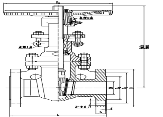
Outline and connect measurement
| Type | DN | L | D | D1 | D2 | b-f | Z-Фd | Hmax | Hmin | D0 | |||
| API(B)Z40H-150LB | 2" | 51 | 178 | 150 | 120.7 | 92.1 | 17.5-2 | 4-Ф19 | 390 | 330 | 200 | ||
| 2 1/2" | 64 | 190 | 180 | 139.7 | 105 | 20.7-2 | 4-Ф19 | 435 | 350 | 200 | |||
| 3" | 77 | 203 | 190 | 152.4 | 127 | 22.3-2 | 4-Ф19 | 510 | 410 | 240 | |||
| 4" | 102 | 229 | 230 | 190.5 | 157 | 22.3-2 | 8-Ф19 | 580 | 465 | 280 | |||
| 5" | 127 | 254 | 255 | 215.9 | 185.7 | 23-2 | 8-Ф22.2 | 660 | 515 | 280 | |||
| 6" | 153 | 267 | 280 | 241.3 | 216 | 23.9-2 | 8-Ф22.2 | 775 | 610 | 320 | |||
| 8" | 204 | 292 | 345 | 298.5 | 270 | 28-2 | 8-Ф22.2 | 965 | 745 | 360 | |||
| 10" | 254 | 330 | 405 | 362 | 323.8 | 28.6-2 | 12-Ф25.4 | 1165 | 890 | 400 | |||
| 12" | 305 | 356 | 485 | 431.8 | 381 | 30.2-2 | 12-Ф25.4 | 1370 | 1040 | 450 | |||
| 14" | 337 | 381 | 535 | 476.3 | 412.8 | 33.4-2 | 12-Ф28.5 | 1545.5 | 1181.5 | 560 | |||
| 16" | 388 | 406 | 595 | 539.8 | 469.9 | 35-2 | 16-Ф28.5 | 1744 | 1326 | 560 | |||
| 18" | 439 | 432 | 635 | 577.9 | 533.4 | 38.1-2 | 16-Ф31.8 | 1930 | 1440 | 640 | |||
| 20" | 489 | 457 | 700 | 635 | 584.2 | 41.3-2 | 20-Ф31.8 | 2135 | 1597 | 640 | |||
| 24" | 591 | 508 | 815 | 749.3 | 692.2 | 46.1-2 | 20-Ф35 | 2531 | 1906.5 | 720 | |||


Get in Touch
Have questions about our products or want to discuss a custom order? Our team is ready to help you.