
HRA85 Hardness Rubber Ceramic Liners Impact Resistant Ceramic Wear Liner
Product Description
HRA85 Hardness Rubber Ceramic Liners Impact Resistant Ceramic Wear Liner
In transfer chutes and hoppers, abrasion is rarely the only problem. Large particles may strike the lining while smaller particles continue sliding across its surface. A hard lining may resist abrasion but crack under repeated impact, while rubber alone may absorb impact but wear too quickly.
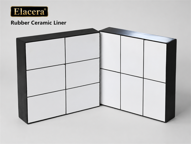
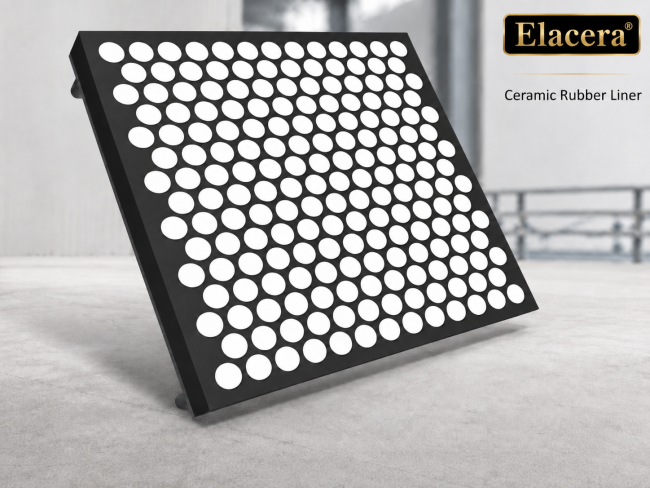
HRA85 hardness rubber ceramic liners combine small alumina ceramic tiles with resilient rubber to manage both wear mechanisms. The ceramic surface protects against sliding abrasion, while the rubber layer absorbs vibration and reduces the peak impact transferred to individual ceramic pieces.
The resulting impact-resistant ceramic wear liner is mainly used in bulk-material handling equipment where abrasion and moderate impact occur together.
HRA85 refers to the hardness of the alumina ceramic—not the rubber. The rubber compound is normally evaluated using Shore A hardness, tensile strength, and elongation.
How the Composite Structure Works
|
Component |
Main Function |
Design Considerations |
|---|---|---|
|
Alumina ceramic tiles |
Resist sliding and cutting abrasion |
Alumina grade, ceramic thickness, tile shape and exposed surface coverage |
|
Rubber matrix |
Absorb impact energy and vibration |
Rubber thickness, Shore hardness, elasticity and operating temperature |
|
Ceramic–rubber interface |
Hold each ceramic piece within the panel |
Vulcanization quality, embedment depth and bond consistency |
|
Equipment connection |
Secure the liner to the chute or hopper |
Bonded installation or customized steel-backed fastening structure |
Small square or hexagonal ceramic pieces allow the rubber matrix to deform locally when material strikes the panel. This helps distribute impact instead of transferring the entire load to one large, rigid ceramic plate.
However, smaller ceramic pieces also create more rubber joints. The ceramic size and arrangement should therefore be selected according to particle size, impact angle, and the balance between abrasion and impact.
Reference Material Properties
Alumina Ceramic
| Property | 92% Alumina Ceramic | 95% Alumina Ceramic |
|---|---|---|
| Alumina Content | ≥92% | ≥95% |
| Density | ≥3.6 g/cm³ | ≥3.8 g/cm³ |
| Rockwell Hardness | ≥82 HRA | ≥85 HRA |
| Fracture Toughness | ≥3.8 MPa·m¹ᐟ² | ≥4.0 MPa·m¹ᐟ² |
| Vickers Hardness | ≥1150 HV10 | ≥1200 HV10 |
| Flexural Strength | ≥290 MPa | ≥330 MPa |
Rubber Layer
|
Property |
General Reference |
|---|---|
|
Tensile Strength |
≥12 MPa |
|
Elongation at Break |
≥250% |
|
Shore A Hardness |
55–65 |
|
Ceramic–Rubber Bond Strength |
≥3.0 MPa |
|
General Temperature Reference |
≤100°C |
These values are general references. Final material properties, dimensions, and test requirements are subject to the confirmed technical specification.
Match the Liner to the Impact Level
A rubber ceramic liner should not be selected from ceramic hardness alone. The most important question is how the material reaches the equipment surface.
| Service Condition | Recommended Design Focus | Main Risk |
|---|---|---|
| Sliding abrasion with limited impact | High ceramic coverage and controlled panel joints | Rapid wear of exposed rubber gaps |
| Combined abrasion and moderate impact | Balanced ceramic and rubber thickness | Ceramic cracking or debonding |
| Repeated vibration | Rubber elasticity and reliable attachment | Panel movement and edge lifting |
| Large lumps or high drop height | Thicker cushioning layer, tougher ceramic and mechanical fastening | Severe ceramic fracture or liner displacement |
| High-temperature material | Temperature resistance of the complete composite | Rubber or adhesive degradation |
For severe impact from large, sharp material or a high vertical drop, a standard rubber ceramic panel may not be sufficient. A thicker rubber layer, larger impact-resistant ceramic shapes, ZTA ceramic, or a steel-backed mechanically fastened liner may need to be evaluated.
Where Rubber Ceramic Liners Usually Fail
1. Unprotected Leading Edges
If the material stream strikes the exposed edge of a panel, it can lift the rubber, damage the first row of ceramic, or open a path beneath the liner.
Panel orientation should be planned so that the material flows across the lining surface instead of directly against an exposed edge.
2. Incorrect Ceramic-to-Rubber Ratio
Adding more rubber does not automatically improve performance. Excessive exposed rubber may wear rapidly under continuous sliding abrasion.
Likewise, using a thin rubber layer beneath large ceramic tiles may provide insufficient cushioning when impact is the dominant problem.
3. Weak Ceramic–Rubber Bonding
Ceramic pieces must remain securely embedded during repeated impact and vibration. Local bonding defects can allow individual ceramic tiles to loosen even when the surrounding panel appears undamaged.
4. Poor Equipment-Surface Preparation
For bonded installation, the steel surface must be clean, dry, and properly prepared. Oil, rust, dust, and loose scale can reduce adhesion between the liner and the equipment shell.
5. Unsupported Panel Joints
Wide gaps or poorly aligned joints expose rubber and steel to concentrated wear. Joints near a direct impact zone require particular attention.
Bonded or Mechanically Fastened?
The product photographs mainly show ceramic tiles embedded in a rubber backing. This type of panel can be bonded directly to a prepared steel surface when the operating conditions and maintenance access are suitable.
For heavier-duty or replaceable installations, the composite liner may be produced with a steel backing plate. The steel-backed version can be fixed using bolts, studs, or a welding structure according to the equipment drawing.
| Installation Method | Suitable Conditions | Points to Check |
|---|---|---|
| Bonded ceramic–rubber panel | Flat or gently curved surfaces under moderate impact | Surface preparation, adhesive selection, curing and edge sealing |
| Bolt-on steel-backed liner | Replaceable lining and heavier impact duties | Bolt location, access from the equipment exterior and protection of fastening points |
| Weld-on steel-backed liner | Permanent installation where external bolting is difficult | Steel backing thickness, weld position and heat control |
The installation method should be confirmed before production because it affects the liner structure, overall thickness, and equipment interface.
Temperature: Check the Rubber, Not Only the Ceramic
Alumina ceramic is produced at high temperature and has good thermal stability, but this does not mean that a rubber ceramic composite liner can operate at the same temperature as a pure ceramic lining.
The operating limit is normally determined by:
- Rubber formulation
- Ceramic–rubber bonding system
- Adhesive used to attach the panel
- Continuous or intermittent heat exposure
- Temperature at the equipment wall
- Thermal cycling during operation
For this product structure, the general rubber temperature reference is up to 100°C. Applications above this range should be reviewed separately. High-temperature pneumatic conveying equipment may require welded ceramic, dovetail ceramic or another mechanically fixed structure without a standard rubber layer.
Typical Equipment
Rubber ceramic liners are commonly considered for:
- Transfer chutes
- Feed and discharge hoppers
- Coal drop chutes
- Vibrating-screen feed boxes
- Conveyor transfer stations
- Storage-bin transition areas
- Crusher feed and discharge sections
- Mineral-processing and bulk-handling equipment
They are used in mining, coal handling, cement, steel, power generation, ports, and other industries where falling or moving material creates both impact and abrasion.
The exact liner structure should be based on the location inside the equipment. A panel suitable for a sliding sidewall may not be suitable for the direct impact zone at the bottom of the same chute.
Manufacturing and Inspection Focus
During production, attention is given to:
- Ceramic grade and tile dimensions
- Ceramic arrangement and exposed surface coverage
- Ceramic embedment in the rubber
- Rubber thickness and panel dimensions
- Ceramic–rubber bonding condition
- Back-surface flatness
- Steel-backing and fastening positions, where applicable
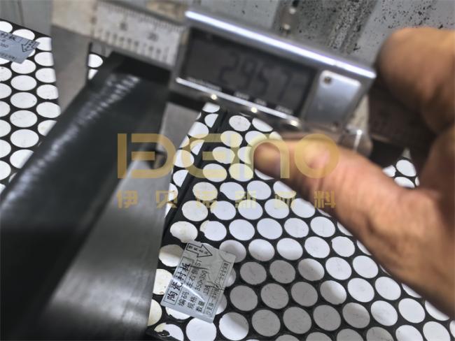
Before delivery, the liner is checked for loose ceramic pieces, visible bonding defects, damaged edges, dimensional deviation, and conformity with the confirmed drawing.
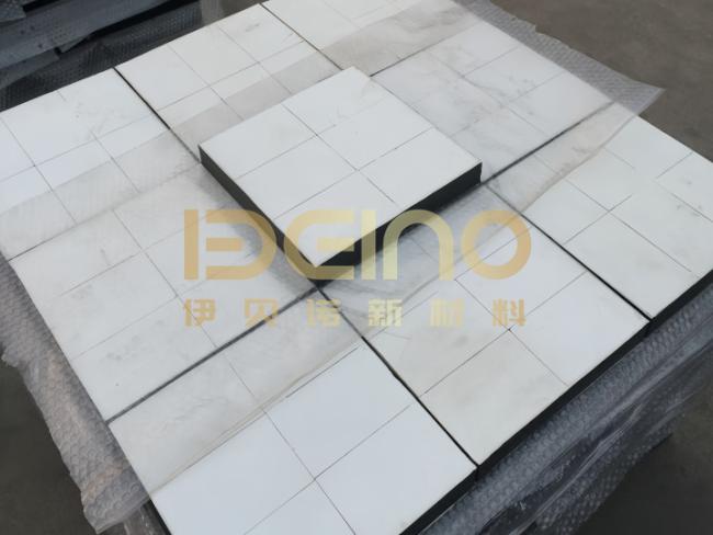
Panels are packed in reinforced wooden cases or on suitable pallets. Ceramic surfaces, corners, and fastening parts are protected to reduce impact and movement during transportation.
Buyer Questions
1. Does HRA85 refer to the rubber hardness?
No. HRA85 refers to the Rockwell A hardness of the alumina ceramic. Rubber hardness is normally measured using the Shore A scale.
2. Why combine ceramic with rubber?
Ceramic provides abrasion resistance, while rubber helps cushion impact and vibration. The combination is useful where both wear mechanisms occur at the same location.
3. Are square tiles or hexagonal tiles better?
Neither shape is automatically better. The selection depends on panel flexibility, ceramic coverage, equipment curvature, particle size and impact direction.
4. Is thicker rubber always better for impact resistance?
No. Rubber thickness must be balanced with ceramic coverage and overall liner thickness. Too much exposed rubber may increase wear under continuous sliding abrasion.
5. Can the liner be used at 300–500°C?
A standard rubber ceramic composite liner is generally not suitable for that temperature range. The rubber and bonding system normally determine the operating limit. High-temperature equipment should use a separately designed ceramic fixing structure.
6. Can the panels be bolted onto the equipment?
Yes, when the liner is manufactured with a suitable steel backing and fastening structure. A rubber-backed panel without a steel plate is normally installed using an approved bonding system.
7. What information is required for liner selection?
Please provide the equipment drawing, liner quantity, material type, maximum particle size, drop height, impact angle, operating temperature, existing wear pattern, and preferred installation method.
A useful starting point is a photograph showing exactly where the existing liner fails. Elacera® can then review whether the problem is caused mainly by sliding abrasion, direct impact, panel-edge exposure, or an unsuitable attachment method.
Get in Touch
Have questions about our products or want to discuss a custom order? Our team is ready to help you.