
M12 Inductive Proximity Sensor with 8mm / 10mm Non-flush Detection and NPN Normally Open (N.O) Output for IP67 Protection
Price:
Negotiable
MOQ:
10 pieces
Delivery Time:
5-8 working days
Brand:
KRONZ
Product Description
M12 Inductive Proximity Sensor NPN N.O — 8mm / 10mm Non-flush | KRONZ
M12 Inductive Proximity Sensor -- NPN Normally Open (N.O) Series
8 mm / 10 mm non-flush detection * 10-30 V DC * IP67 * 4-pin M12 connector
8 mm / 10 mm non-flush detection * 10-30 V DC * IP67 * 4-pin M12 connector
Built for Japanese PLCs and current-sinking input modules. When metal enters the detection range, the output pulls down to 0 V -- directly compatible with sink-type inputs on Mitsubishi, Omron and other Japanese PLCs without any level shifter.
Models on this page: IN8-M12NO68-M0A/D, IN8-M12NO50-M0A/D, IN10-M12NO68-M0A/D, IN10-M12NO50-M0A/D
Product Overview
What this series solves
On any production line there are three questions the operator keeps asking: is the part here, has the mechanism reached its end-stop, has the gripper closed? All three reduce to one detection: is a metal object in a specific position. An NPN normally-open proximity sensor gives a direct answer -- no metal = output open, metal present = output closed.
How NPN N.O works
NPN output is also called current sinking. Inside the sensor is an NPN transistor whose emitter is tied to 0 V (L−):
- No metal target → transistor off → output pin is high-impedance → no current through the load → PLC input reads "0"
- Metal enters the range → transistor on → output pin is pulled to ~0 V, current flows from L+ through the load into the output pin → PLC input reads "1"
The load is wired between L+ (brown, Pin 1) and OUT (black, Pin 4). Current flows into the output pin -- that is the sink behavior.
When to choose NPN N.O
| Your situation | Choose it? |
|---|---|
| PLC input module is sink / common-plus (COM tied to 24 V+) | ✅ |
| You use Mitsubishi, Omron, Keyence or similar Japanese PLCs | ✅ |
| You want a logic that reads "target arrived = ON" | ✅ |
| PLC is source / common-minus | ❌ pick PNP N.O |
| You need fail-safe -- broken wire must trigger an alarm | ❌ pick NPN N.C |
IN8 vs IN10 -- how to pick between the two distances
- IN8 series -- 8 mm detection range, 500 Hz switching -- faster response, ideal for high-speed counting and small-part detection
- IN10 series -- 10 mm detection range, 400 Hz switching -- more installation margin when the target vibrates or the mounting surface is uneven
Both share the M12 × 1 mm cylindrical thread and non-flush (unshielded) installation. Same datasheet, same mounting logic -- only the detection range and switching frequency differ.
Key Features
1. NPN current-sinking output, direct to Japanese PLCs
Wire the output straight into the sink input of a Mitsubishi FX/Q, Omron CP/CJ, or Keyence module. No interposing relay, no level shifter. You save the cost of one relay and one wiring failure point.
Wire the output straight into the sink input of a Mitsubishi FX/Q, Omron CP/CJ, or Keyence module. No interposing relay, no level shifter. You save the cost of one relay and one wiring failure point.
2. Normally-open logic, easy to read on the floor
No metal → LEDs off, output open. Metal present → 4 × LEDs light and output closes. During commissioning you don't need to check the manual -- just look at the LEDs.
No metal → LEDs off, output open. Metal present → 4 × LEDs light and output closes. During commissioning you don't need to check the manual -- just look at the LEDs.
3. Two detection ranges on one page
Choose 8 mm at 500 Hz for high-speed applications, or 10 mm at 400 Hz when the target has more play.
Choose 8 mm at 500 Hz for high-speed applications, or 10 mm at 400 Hz when the target has more play.
4. Non-flush (unshielded) -- longer range from the same M12 footprint
The unshielded structure lets the magnetic field spread sideways, giving a longer rated range than the flush variant in the same M12 body. The trade-off is that you must keep free metal space around the sensing face.
The unshielded structure lets the magnetic field spread sideways, giving a longer rated range than the flush variant in the same M12 body. The trade-off is that you must keep free metal space around the sensing face.
5. IP67 + −25…70 °C -- survives the shop floor
IP67 per IEC 60529: dust-tight and protected against temporary immersion. Cutting fluid, coolant splash, and metal dust are all in spec. The −25…70 °C operating range covers cold storage to cabinet-side mounting.
IP67 per IEC 60529: dust-tight and protected against temporary immersion. Cutting fluid, coolant splash, and metal dust are all in spec. The −25…70 °C operating range covers cold storage to cabinet-side mounting.
6. Nickel-plated brass body + PBT sensing face
The housing is nickel-plated brass for impact and corrosion resistance. The sensing face is blue PBT -- wear-resistant and insensitive to metal swarf. Two hex nuts (17 mm across flats) clamp the sensor and resist long-term vibration loosening.
The housing is nickel-plated brass for impact and corrosion resistance. The sensing face is blue PBT -- wear-resistant and insensitive to metal swarf. Two hex nuts (17 mm across flats) clamp the sensor and resist long-term vibration loosening.
7. Field-replaceable M12 connector
The 4-pin M12 A-coded male connector (IEC 61076-2-101) is not a fixed cable. If the cable gets damaged, just swap the cordset -- no need to disassemble the sensor or re-wire it.
The 4-pin M12 A-coded male connector (IEC 61076-2-101) is not a fixed cable. If the cable gets damaged, just swap the cordset -- no need to disassemble the sensor or re-wire it.
8. Triple electrical protection -- hard to kill during commissioning
Built-in short-circuit, reverse-polarity and power-up pulse protection. If you accidentally reverse the 24 V supply or short the output to ground, the sensor protects itself and resumes operation once the fault is cleared.
Built-in short-circuit, reverse-polarity and power-up pulse protection. If you accidentally reverse the 24 V supply or short the output to ground, the sensor protects itself and resumes operation once the fault is cleared.
Technical Specifications
Common electrical parameters (all 4 models)
| Parameter | Specification | Standard |
|---|---|---|
| Output function | NPN, Normally Open (N.O) | IEC 60947-5-2 |
| Output configuration | DC 3-wire | IEC 60947-5-2 |
| Thread / form factor | M12 × 1 mm cylindrical | -- |
| Installation type | Non-flush (unshielded) | IEC 60947-5-2 |
| Operating voltage | 10…30 V DC (±10%) | IEC 60947-5-2 |
| Voltage drop | ≤ 2.0 V | IEC 60947-5-2 |
| Rated operating current | 200 mA | IEC 60947-5-2 |
| Leakage current | ≤ 0.01 mA | IEC 60947-5-2 |
| No-load current | ≤ 10 mA (at 24 V DC) | IEC 60947-5-2 |
| Switching hysteresis | < 15% of Sr | IEC 60947-5-2 |
| Repeat accuracy | < 1.0% of Sr | IEC 60947-5-2 |
| Electrical protection | Short-circuit / reverse-polarity / power-up pulse | IEC 60947-5-2 |
| Switching-state indication | 4 × LEDs, on while output is active | -- |
| Connection | 4-pin M12 connector, A-coded | IEC 61076-2-101 |
Per-model differences (key selection parameters)
| Model | Sensing range Sn | Switching freq. | Body length | Thread length | Total length (straight) | 90° height |
|---|---|---|---|---|---|---|
| IN8-M12NO68-M0A/D | 8 mm (non-flush) | 500 Hz | 68 mm | 42 mm | 68 mm | 34 mm |
| IN8-M12NO50-M0A/D | 8 mm (non-flush) | 500 Hz | 50 mm | 28 mm | 50 mm | 20 mm |
| IN10-M12NO68-M0A/D | 10 mm (non-flush) | 400 Hz | 68 mm | 42 mm | 68 mm | 34 mm |
| IN10-M12NO50-M0A/D | 10 mm (non-flush) | 400 Hz | 50 mm | 28 mm | 50 mm | 20 mm |
Shared across all four: M12 × 1 mm thread, Ø7 mm sensing face, 67 mm barrel length (68-body) or 49 mm (50-body), 17 mm nut across flats.
Mechanical and environmental parameters
| Parameter | Specification | Standard |
|---|---|---|
| Ambient operating temperature | −25 … +70 °C | IEC 60068-2-14 |
| Ingress protection | IP67 (dust-tight, protected against temporary immersion) | IEC 60529 |
| Housing material | Brass, nickel-plated | -- |
| Sensing face material | PBT (polybutylene terephthalate) | -- |
| Connector thread | M12 × 1 mm male | IEC 61076-2-101 |
| Mounting hardware | Two hex nuts, 17 mm across flats | -- |
NPN N.O output truth table
| Metal target | Output transistor | Output pin level | LEDs | PLC input |
|---|---|---|---|---|
| Not in range | Off (high-Z) | Pulled up to L+ | Off | 0 |
| Enters range | On | ≈ 0 V | Lit | 1 |
Configuration Details
Model selection
| Model | Range | Frequency | Body | Recommended use |
|---|---|---|---|---|
| IN8-M12NO68-M0A/D | 8 mm | 500 Hz | 68 mm | High-speed counting, small-part detection, standard stations |
| IN8-M12NO50-M0A/D | 8 mm | 500 Hz | 50 mm | Slim fixtures, tight machine frames |
| IN10-M12NO68-M0A/D | 10 mm | 400 Hz | 68 mm | Targets that vibrate or have wide position tolerance |
| IN10-M12NO50-M0A/D | 10 mm | 400 Hz | 50 mm | Limited space but 10 mm range required |
Pin assignment -- 4-pin M12 A-coded
| Pin | Wire colour (typical) | Signal | Description |
|---|---|---|---|
| 1 | Brown | L+ | Supply positive, 10…30 V DC |
| 2 | White | N/C | Not connected (reserved) |
| 3 | Blue | L− | Supply 0 V (GND) |
| 4 | Black | OUT | NPN Normally Open (N.O) switching output |
The factory datasheet does not include a wiring diagram. The table above follows the M12 4-pin A-coded convention (IEC 61076-2-101). Verify against the wiring label packed with the sensor before commissioning.
Wiring diagram -- NPN N.O
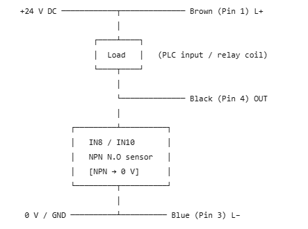
Key point: The load sits between L+ and OUT. When the sensor closes, it sinks the output pin to 0 V, completing the current path. This is the source-and-sink (sink) wiring.
Dimensions (mm)
| Dimension | 68 mm body | 50 mm body |
|---|---|---|
| Total length (straight M12 connector) | 68 | 50 |
| Barrel length (to connector shoulder) | 67 | 49 |
| Threaded section length | 42 | 28 |
| Sensing face diameter | Ø7 | Ø7 |
| 90° right-angle connector height | 34 | 20 |
| Mounting thread | M12 × 1 mm | M12 × 1 mm |
| Nut across flats | 17 | 17 |
Mounting requirements (non-flush)
- Free metal space around the sensing face. Non-flush (unshielded) sensors let the magnetic field expand sideways. Without sufficient clearance, the effective detection range collapses. Recommended free space ≥ 3 × Sn (≈ 24 mm for the 8 mm body, ≈ 30 mm for the 10 mm body). When mounting two sensors side by side, also keep enough spacing to prevent mutual interference.
- If you must flush-mount. This series is unshielded. If the installation cannot provide side clearance, switch to a flush (shielded) variant instead.
- Tightening torque. Clamp with the two hex nuts. Do not over-tighten -- suggested maximum is 15 N*m to avoid housing deformation.
- Temperature drift. Datasheet repeat accuracy is < 1.0% Sr and hysteresis < 15% Sr. Allow margin for tight-positioning applications where temperature varies across the −25…70 °C range.
Typical applications
| Industry | Use case |
|---|---|
| Industrial automation | Part-presence detection on conveyors, station confirmation on assembly lines |
| Packaging machinery | Carton and foil position verification, flap-in-place check |
| Material handling | Pallet, tote and shuttle positioning |
| Machine tools | End-stop detection, tool-changer position feedback |
| Robotics | Gripper open/close confirmation, axis end-position homing |
Related variants in the same M12 series
| Output function | Description |
|---|---|
| NPN Normally Closed (N.C) | Output closed when no target -- for fail-safe circuits and wire-break detection |
| PNP Normally Open (N.O) | Current-sourcing output, fits other European PLCs |
| PNP Normally Closed (N.C) | Sourcing + fail-safe |
Similar Products
Get in Touch
Have questions about our products or want to discuss a custom order? Our team is ready to help you.
Company
Kronz (guangzhou) Electronics Co., Ltd.
Location
Floor 7, Building 12B, Hanhe Robot Intelligent Manufacturing Base Exhibition Center, Xiangshan Avenue, Zengcheng Economic Development Zone, Guangzhou, Guangdong Province, China
Contact Person
Doris