
DE Series Free Stop Cam Indexer with Flange Type Design for Pharmaceutical Field Applications
Price:
200 $/SET~4500 $/SET
MOQ:
≥1000 $
Delivery Time:
4 DAYS-20 DAYS
Brand:
HONEPAN
Product Description
DE/DFS Series Free Stop Cam Indexer
Arbitrary Stop Cam Indexing Gears
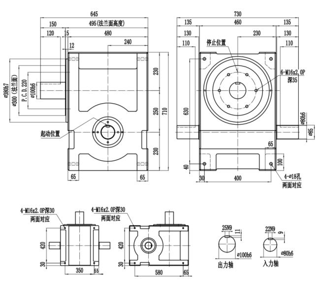
The DE series mandrel flange divider combines the optimal characteristics of both flange type dividers and mandrel type cam indexers. This versatile indexing solution is engineered for precision performance in demanding industrial applications.
Key Applications
Specifically designed for high-precision production environments, the DE/DFS Series excels in:
- Pharmaceutical manufacturing systems
- Liquid filling and packaging lines
- Automated assembly processes
- Precision indexing applications requiring free-stop capability
According to the distance between the input shaft and the output shaft, the size of the cabinet, and the size of the load that can be withstood, it can be divided into: 45DE/60DE/70DE/80DE/100DE/110DE/125DE/140DE/150DE/180DE/200DE/250DE
| 45DE | |||
| Item | Symbol | Unit | Value |
|---|---|---|---|
| Allowable Radial Load of Output Shaft | C1 | kgf | 128 |
| Allowable Axial Load of Output Shaft | C2 | kgf | 138 |
| Allowable Torque of Output Shaft | Ts | kgf-m | Refer to Torque Table |
| Allowable Radial Load of Input Shaft | C3 | kgf | 83 |
| Maximum Bending Moment of Input Shaft | C4 | kgf | 108 |
| Maximum Torque of Input Shaft | C5 | kgf-m | 3.8 |
| Moment of Inertia of Input Shaft (Note 1) | C6 | kgf-m2 | 3.2×10⁻⁴ |
| Positioning Indexing Accuracy | sec. | ±30 | |
| Weight | kg | 9 | |

| 60DE | |||
| Item | Symbol | Unit | Value |
|---|---|---|---|
| Allowable Radial Load of Output Shaft | C1 | kgf | 138 |
| Allowable Axial Load of Output Shaft | C2 | kgf | 140 |
| Allowable Torque of Output Shaft | Ts | kgf-m | Refer to Torque Table |
| Allowable Radial Load of Input Shaft | C3 | kgf | 97 |
| Maximum Bending Moment of Input Shaft | C4 | kgf | 148 |
| Maximum Torque of Input Shaft | C5 | kgf-m | 5.8 |
| Moment of Inertia of Input Shaft (Note 1) | C6 | kgf-m2 | 1.9×10⁻³ |
| Positioning Indexing Accuracy | sec. | ±30 | |
| Weight | kg | 15 | |

| 70DE | |||
| Item | Symbol | Unit | Value |
|---|---|---|---|
| Allowable Radial Load of Output Shaft | C1 | kgf | 218 |
| Allowable Axial Load of Output Shaft | C2 | kgf | 298 |
| Allowable Torque of Output Shaft | Ts | kgf-m | Refer to Torque Table |
| Allowable Radial Load of Input Shaft | C3 | kgf | 146 |
| Maximum Bending Moment of Input Shaft | C4 | kgf | 105 |
| Maximum Torque of Input Shaft | C5 | kgf-m | 9 |
| Moment of Inertia of Input Shaft (Note 1) | C6 | kgf-m2 | 6×10⁻³ |
| Positioning Indexing Accuracy | sec. | ±30 | |
| Weight | kg | 20 | |

| 80DE | |||
| Item | Symbol | Unit | Value |
|---|---|---|---|
| Allowable Radial Load of Output Shaft | C1 | kgf | 327 |
| Allowable Axial Load of Output Shaft | C2 | kgf | 417 |
| Allowable Torque of Output Shaft | Ts | kgf-m | Refer to Torque Table |
| Allowable Radial Load of Input Shaft | C3 | kgf | 345 |
| Maximum Bending Moment of Input Shaft | C4 | kgf | 255 |
| Maximum Torque of Input Shaft | C5 | kgf-m | 24 |
| Moment of Inertia of Input Shaft (Note 1) | C6 | kgf-m2 | 9×10⁻³ |
| Positioning Indexing Accuracy | sec. | ±30 | |
| Weight | kg | 35 | |

| 100DE | |||
| Item | Symbol | Unit | Value |
|---|---|---|---|
| Allowable Radial Load of Output Shaft | C1 | kgf | 500 |
| Allowable Axial Load of Output Shaft | C2 | kgf | 650 |
| Allowable Torque of Output Shaft | Ts | kgf-m | Refer to Torque Table |
| Allowable Radial Load of Input Shaft | C3 | kgf | 400 |
| Maximum Bending Moment of Input Shaft | C4 | kgf | 395 |
| Maximum Torque of Input Shaft | C5 | kgf-m | 34 |
| Moment of Inertia of Input Shaft (Note 1) | C6 | kgf-m2 | 4×10⁻³ |
| Positioning Indexing Accuracy | sec. | ±30 | |
| Weight | kg | 55 | |

| 110DE | |||
| Item | Symbol | Unit | Value |
|---|---|---|---|
| Allowable Radial Load of Output Shaft | C1 | kgf | 555 |
| Allowable Axial Load of Output Shaft | C2 | kgf | 695 |
| Allowable Torque of Output Shaft | Ts | kgf-m | Refer to Torque Table |
| Allowable Radial Load of Input Shaft | C3 | kgf | 475 |
| Maximum Bending Moment of Input Shaft | C4 | kgf | 410 |
| Maximum Torque of Input Shaft | C5 | kgf-m | 39 |
| Moment of Inertia of Input Shaft (Note 1) | C6 | kgf-m2 | 2.8×10⁻² |
| Positioning Indexing Accuracy | sec. | ±30 | |
| Weight | kg | 68 | |

| 125DE | |||
| Item | Symbol | Unit | Value |
|---|---|---|---|
| Allowable Radial Load of Output Shaft | C1 | kgf | 630 |
| Allowable Axial Load of Output Shaft | C2 | kgf | 850 |
| Allowable Torque of Output Shaft | Ts | kgf-m | Refer to Torque Table |
| Allowable Radial Load of Input Shaft | C3 | kgf | 520 |
| Maximum Bending Moment of Input Shaft | C4 | kgf | 560 |
| Maximum Torque of Input Shaft | C5 | kgf-m | 65 |
| Moment of Inertia of Input Shaft (Note 1) | C6 | kgf-m2 | 0.28 |
| Positioning Indexing Accuracy | sec. | ±30 | |
| Weight | kg | 78 | |

| 140DE | |||
| Item | Symbol | Unit | Value |
|---|---|---|---|
| Allowable Radial Load of Output Shaft | C1 | kgf | 755 |
| Allowable Axial Load of Output Shaft | C2 | kgf | 995 |
| Allowable Torque of Output Shaft | Ts | kgf-m | Refer to Torque Table |
| Allowable Radial Load of Input Shaft | C3 | kgf | 545 |
| Maximum Bending Moment of Input Shaft | C4 | kgf | 705 |
| Maximum Torque of Input Shaft | C5 | kgf-m | 98 |
| Moment of Inertia of Input Shaft (Note 1) | C6 | kgf-m2 | 0.11 |
| Positioning Indexing Accuracy | sec. | ±30 | |
| Weight | kg | 92 | |

| 150DE | |||
| Item | Symbol | Unit | Value |
|---|---|---|---|
| Allowable Radial Load of Output Shaft | C1 | kgf | 760 |
| Allowable Axial Load of Output Shaft | C2 | kgf | 1000 |
| Allowable Torque of Output Shaft | Ts | kgf-m | Refer to Torque Table |
| Allowable Radial Load of Input Shaft | C3 | kgf | 550 |
| Maximum Bending Moment of Input Shaft | C4 | kgf | 710 |
| Maximum Torque of Input Shaft | C5 | kgf-m | 100 |
| Moment of Inertia of Input Shaft (Note 1) | C6 | kgf-m2 | 0.11 |
| Positioning Indexing Accuracy | sec. | ±30 | |
| Weight | kg | 94 | |

| 180DE | |||
| Item | Symbol | Unit | Value |
|---|---|---|---|
| Allowable Radial Load of Output Shaft | C1 | kgf | 1195 |
| Allowable Axial Load of Output Shaft | C2 | kgf | 1495 |
| Allowable Torque of Output Shaft | Ts | kgf-m | Refer to Torque Table |
| Allowable Radial Load of Input Shaft | C3 | kgf | 1095 |
| Maximum Bending Moment of Input Shaft | C4 | kgf | 1955 |
| Maximum Torque of Input Shaft | C5 | kgf-m | 336 |
| Moment of Inertia of Input Shaft (Note 1) | C6 | kgf-m2 | 0.39 |
| Positioning Indexing Accuracy | sec. | ±30 | |
| Weight | kg | 225 | |

| 200DE | |||
| Item | Symbol | Unit | Value |
|---|---|---|---|
| Allowable Radial Load of Output Shaft | C1 | kgf | 1210 |
| Allowable Axial Load of Output Shaft | C2 | kgf | 1510 |
| Allowable Torque of Output Shaft | Ts | kgf-m | Refer to Torque Table |
| Allowable Radial Load of Input Shaft | C3 | kgf | 1105 |
| Maximum Bending Moment of Input Shaft | C4 | kgf | 1965 |
| Maximum Torque of Input Shaft | C5 | kgf-m | 341 |
| Moment of Inertia of Input Shaft (Note 1) | C6 | kgf-m2 | 0.39 |
| Positioning Indexing Accuracy | sec. | ±30 | |
| Weight | kg | 240 | |

| 250DE | |||
| Item | Symbol | Unit | Value |
|---|---|---|---|
| Allowable Radial Load of Output Shaft | C1 | kgf | 3195 |
| Allowable Axial Load of Output Shaft | C2 | kgf | 4145 |
| Allowable Torque of Output Shaft | Ts | kgf-m | Refer to Torque Table |
| Allowable Radial Load of Input Shaft | C3 | kgf | 1545 |
| Maximum Bending Moment of Input Shaft | C4 | kgf | 3795 |
| Maximum Torque of Input Shaft | C5 | kgf-m | 775 |
| Moment of Inertia of Input Shaft (Note 1) | C6 | kgf-m2 | 1.98 |
| Positioning Indexing Accuracy | sec. | ±30 | |
| Weight | kg | 695 | |
Similar Products
Get in Touch
Have questions about our products or want to discuss a custom order? Our team is ready to help you.
Company
Zhucheng HONEPAN Automation Machinery Factory
Location
No. 8 HonePan Road, Zhenxi Industrial Park, Huanghua Tow , Zhucheng City, Shandong Province,China.
Contact Person
Sean