ACSR Aluminum Conductor Steel Reinforced Overhead Bare 185 / 30mm2 IEC61089
ACSR 185/30mm2 overhead bare conductor aluminum conductor steel reinforced IEC61089
Application
ACSR are usually used as bare overhead transmission cable and as primary and secondary distribution cable. They have a long service record because of its economy, dependability, and strength to weight ratio.
Bare Conductor Electrical Cable STANDARD
Basic design to BS 215-2 / BS EN 50182 / IEC 61089 / ASTM B 232/B 232M / DIN 48204 / JIS C 3110 standards.
Note: The values of current rating mentioned in above Table are based on wind velocity of 0.6 metre/second, solar heat radiation of 1200 watt/metre2, ambient temperature of 50° C & conductor temperature of 80°C.
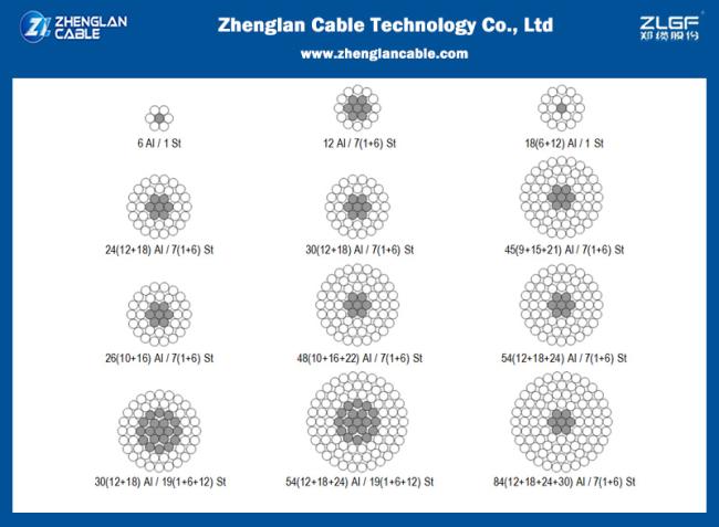
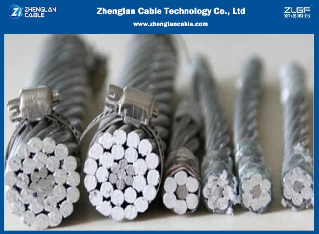
Bare Conductor Electrical Cable CONSTRUCTION
ACSR conductors are formed by several wires of aluminium and galvanized steel, stranded in concentric layers. The wire or wires which form the core, are made of galvanized steel and the external layer or layers, are of aluminium. Galvanized steel core consist normally of 1, 7 or 19 wires. The diameters of steel and aluminium wires can be the same, or different.
By varying the relative proportions of aluminium and steel, the required characteristics for any particular application can be reached. A higher U. T. S. Can be obtained, by increasing steel content, and a higher current carrying capacity by increasing aluminium content.
ELECTRICAL PROPERTIES
| density@20ºC | Aluminium: 2.703 kg/dm |
| Galvanised Steel: 7.80 kg/dm | |
| Temperature Coefficient@20°C | Aluminium: 0.00403 (°C) |
| resistivity@20°C | Aluminium: Should not exceed 0.028264 |
|
linear Expansivity
|
Aluminium: 23 x10 (°C) |
| Galvanised Steel: 11.5 x10 (1/°C) |
SERVICE CONDITIONS
| Ambient Temperature | -5°C - 50°C |
| Wind Pressure | 80 – 130kg/m |
| Seismic Acceleration | 0.12 - 0.05g |
| Isokeraunic level | 10 – 18 |
| relative Humidity | 5 – 100% |
TECHNICAL DATA
| Numbers of Wires | Modules of Elasticity | Coeficient of linear Expansion | |||
| AL | STEEL | Kg/mm2 | Lb/in2 | 1/Cº | 1/Fº |
| 6 | 1 | 81 | 11.5 x10⁶ | 19.1 x10⁻⁶ | 10.6 x10⁻⁶ |
| 6 | 7 | 77 | 11.0 x10⁶ | 19.8 x10⁻⁶ | 11.0 x10⁻⁶ |
| 12 | 7 | 107 | 15.2 x10⁶ | 15.3 x10⁻⁶ | 8.5 x10⁻⁶ |
| 18 | 1 | 67 | 9.5 x10⁶ | 21.2 x10⁻⁶ | 11.8 x10⁻⁶ |
| 24 | 7 | 74 | 10.5 x10⁶ | 19.6 x10⁻⁶ | 10.9 x10⁻⁶ |
| 26 | 7 | 77 | 10.9 x10⁶ | 18.9 x10⁻⁶ | 10.5 x10⁻⁶ |
| 28 | 7 | 79 | 11.2 x10⁶ | 18.4 x10⁻⁶ | 10.2 x10⁻⁶ |
| 30 | 7 | 82 | 11.6 x10⁶ | 17.8 x10⁻⁶ | 9.9 x10⁻⁶ |
| 30 | 19 | 80 | 11.4 x10⁶ | 18.0 x10⁻⁶ | 10.0 x10⁻⁶ |
| 32 | 19 | 82 | 11.7 x10⁶ | 17.5 x10⁻⁶ | 9.7 x10⁻⁶ |
| 54 | 7 | 70 | 9.9 x10⁶ | 19.3 x10⁻⁶ | 10.7 x10⁻⁶ |
| 54 | 19 | 68 | 9.7 x10⁶ | 19.4 x10⁻⁶ | 10.8 x10⁻⁶ |
Parameters
| Code | Nominal Area | Stranding | Overall Diameter | Weight | Breaking Load |
Electrical Resistance @20° |
|||
| AL | STEEL | TOTAL | AL | STEEL | |||||
| mm2 | mm2 | mm2 | No.xmm | No.xmm | mm | Kg/Km | KN | Ω/Km | |
| 16 | 16 | 2.56 | 18.7 | 6/1.84 | 1/1.84 | 5.53 | 64.6 | 6.08 | 1.7934 |
| 25 | 25 | 4.17 | 29.2 | 6/2.30 | 1/2.30 | 6.9 | 100.9 | 9.13 | 1.1478 |
| 40 | 40 | 6.67 | 46.7 | 6/2.91 | 1/2.91 | 8.73 | 161.5 | 14.4 | 0.7174 |
| 63 | 63 | 10.5 | 73.5 | 6/3.66 | 1/3.66 | 10.98 | 254.4 | 21.63 | 0.4555 |
| 100 | 100 | 16.7 | 117 | 6/4.61 | 1/4.61 | 13.83 | 403.8 | 34.33 | 0.2869 |
| 125 | 125 | 6.94 | 132 | 18/2.97 | 1/2.97 | 14.85 | 397.9 | 29.17 | 0.2304 |
| 125 | 125 | 20.4 | 145 | 26/2.47 | 7/1.92 | 15.64 | 503.9 | 45.69 | 0.231 |
| 160 | 160 | 8.89 | 169 | 18/3.36 | 1/3.36 | 16.8 | 509.3 | 36.18 | 0.18 |
| 160 | 160 | 26.1 | 186 | 26/2.80 | 7/2.18 | 17.74 | 644.9 | 57.69 | 0.1805 |
| 200 | 200 | 11.1 | 211 | 18/3.76 | 1/3.76 | 18.8 | 636.7 | 44.22 | 0.144 |
| 200 | 200 | 32.6 | 233 | 26/3.13 | 7/2.43 | 19.81 | 806.2 | 70.13 | 0.1444 |
| 250 | 250 | 24.6 | 275 | 22/3.80 | 7/2.11 | 21.53 | 880.6 | 68.72 | 0.1154 |
| 250 | 250 | 40.7 | 291 | 26/3.50 | 7/2.72 | 22.16 | 1007.7 | 87.67 | 0.1155 |
| 315 | 315 | 21.8 | 337 | 45/2.99 | 7/1.99 | 23.91 | 1039.6 | 79.03 | 0.0917 |
| 315 | 315 | 51.3 | 366 | 26/3.93 | 7/3.05 | 24.87 | 1269.7 | 106.83 | 0.0917 |
| 400 | 400 | 27.7 | 428 | 45/3.36 | 7/2.24 | 26.88 | 1320.1 | 98.36 | 0.0722 |
| 400 | 400 | 51.9 | 452 | 54/3.07 | 7/3.07 | 27.63 | 1510.3 | 123.04 | 0.0723 |
| 450 | 450 | 31.1 | 481 | 45/3.57 | 7/2.38 | 28.56 | 1485.2 | 107.47 | 0.0642 |
| 450 | 450 | 58.3 | 508 | 54/3.26 | 7/3.26 | 29.34 | 1699.1 | 138.42 | 0.0643 |
| 500 | 500 | 34.6 | 535 | 45/3.76 | 7/2.51 | 30.09 | 1650.2 | 119.41 | 0.0578 |
| 500 | 500 | 64.8 | 565 | 54/3.43 | 7/3.43 | 30.87 | 1887.9 | 153.8 | 0.0578 |
| 560 | 560 | 38.7 | 599 | 45/3.98 | 7/2.65 | 31.83 | 1848.2 | 133.74 | 0.0516 |
| 560* | 560 | 70.9 | 631 | 54/3.63 | 19/2.18 | 32.68 | 2103.4 | 172.59 | 0.0516 |
| 630 | 630 | 43.6 | 674 | 45/4.22 | 7/2.81 | 33.75 | 2079.2 | 150.45 | 0.0459 |
| 630* | 630 | 79.8 | 710 | 54/3.85 | 19/2.31 | 34.65 | 2366.3 | 191.77 | 0.0459 |
| 710 | 710 | 49.1 | 759 | 45/4.48 | 7/2.99 | 35.85 | 2343.2 | 169.56 | 0.0407 |
| 710* | 710 | 89.9 | 800 | 54/4.09 | 19/2.45 | 36.79 | 2666.8 | 216.12 | 0.0407 |
| 800* | 800 | 34.6 | 835 | 72/3.76 | 7/2.51 | 37.61 | 2480.2 | 167.41 | 0.0361 |
| 800* | 800 | 66.7 | 867 | 84/3.48 | 7/3.48 | 38.28 | 2732.7 | 205.33 | 0.0362 |
| 800* | 800 | 101 | 901 | 54/4.34 | 19/2.61 | 39.09 | 3004.9 | 243.52 | 0.0362 |
| 900* | 900 | 38.9 | 939 | 72/3.99 | 7/2.66 | 39.9 | 2790.2 | 188.33 | 0.0321 |
| 900* | 900 | 75 | 975 | 84/3.69 | 7/3.69 | 40.59 | 3074.2 | 226.5 | 0.0322 |
| 1000* | 1000 | 43.2 | 1043 | 72/4.21 | 7/2.80 | 42.08 | 3100.3 | 209.26 | 0.0289 |
- overhead transmission line use bare conductor(ACSR, AAC, AAAC etc)
- 1-35kv overhead transmission line use insulated conductor
- power distribution use 0.6/1kv, 1.8/3kv PVC/XLPE/PE insulated LV(low voltage) power cable armored or unarmored
- power distribution use 3.6/6kv, 6/10kv,8.7/10kv, 8.7/15kv, 12/20kv, 21/35kv, 26/35kv XLPE insulated MV(medium voltage) power cable armored or unarmored;
- 300/300V, 300/500V, 450/750V cotrol cable, house wire


Get in Touch
Have questions about our products or want to discuss a custom order? Our team is ready to help you.