
High Precision DLC Ezcad Laser Control Card Laser Marking Systems CE Listed
DLC2 (DSP Laser Control Electronics-2) board instruction
The DLC2 control board and EZCAD3 software can perform real-time synchronous control of 2D/3D scanning galvanometer and laser.
The main features of the board are as follows:
(1) Support enhanced version of the XY2-100 data protocol (X, Y, Z triaxial galvanometer)
(2) Supports fiber, CO2, QCW, SPI, UV, YAG and other lasers through the laser expansion card
(3) Support 10 input and 8 output ports
(4) 12V power supply, minimum current requirement 3A
(5) Support flight marking function
(6) Support offline marking function
(7) Support 16Bit/18Bit galvanometer, which can be customized according to the actual galvanometer protocol
The board interface is as follows:
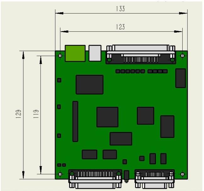
Figure 1 Board size
The board has two LED indicators. After the board is powered on, the green light is always on. The red light is on when the laser light is controlled during the marking process.
Interface function:
CON1: power interface, 2P green terminal socket;
CON2: laser interface, support all lasers, DB25 socket (female);
CON3: galvanometer interface, support enhanced XY2-100 data protocol, can drive 2D/3D galvanometer, DB15 socket;
CON5: IO interface for flight marking interface, input and output digital signals, DB37 socket.

Description:
There are two output modes for the pulse and direction signals output by the board: differential output and common anode (TTL) output, which are selected by jumpers JP1-JP8, defined as below:
(1) When the 2-3 pins of the jumper are shorted, the pulse and direction signals are differential outputs, and the PIN2 is pulse-, PIN6 is pulse+, PIN3 is direction-, PIN7 is direction+, which signals are respectively connected to The PUL-, PUL+, DIR- and DIR+ signals of the driver.
(2) When the 1-2 pins of the jumper are shorted, the pulse and direction signals are common anode output, the PIN1 is VCC, and is connected to the VCC of the driver, the pulse of the PIN6 is + and the PIN7 is connected to the PUL and DIR of the driver respectively.
Note: When using EZCAD3 software with DLC2-M4, open Motors.ini in the EZCAD3 software folder "PARAM" to find m_bUse9030=1 to enable the 9030 motion control card, m_bUse9030=0 means that the M4 motion control card is enabled.

Get in Touch
Have questions about our products or want to discuss a custom order? Our team is ready to help you.