Electrical Airborne Heavy Duty Flexible Retractable Fencing Boom Barrier Remote Control Gate
Price:
negotiable
MOQ:
Sample order accepted
Delivery Time:
5-10 working days after payment received
Brand:
SINOMATIC
Product Description
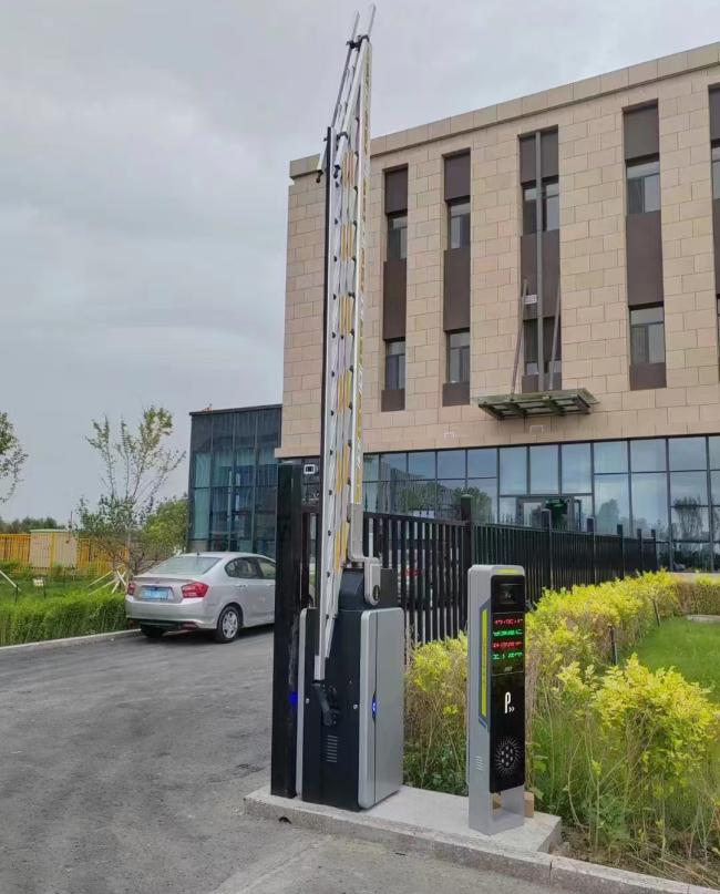
Electrical Airborne Heavy Duty Flexible Retractable Fencing Boom Barrier Remote Control Gate
This heavy-duty boom barrier gate features a robust four-part construction consisting of housing, transmission mechanism, control unit, and boom. Designed for universal installation without left/right distinction, it provides reliable vehicle access management for residential areas, commercial properties, and institutional facilities.
Key Features
- Motor-driven with connecting rod transmission mechanism and balance spring for stable, reliable operation
- Motor lifespan exceeding 2.5 million cycles with spring life of 400,000 cycles
- Standard obstacle rebound function automatically reverses boom when obstructed during descent
- Supports external radar, coil, and infrared anti-smash functions
- Built-in DC 12V power supply output for external radar power
- RS485 communication and parallel connection support
Technical Specifications
| Housing Dimension | 530×487×1400mm |
|---|---|
| Motor Type | BLDC Motor |
| Motor Power | 180W |
| Total Length | 6m (including housing) |
| Boom Useful Length | ≤ 5.47m |
| Opening/Closing Time | 4s~9s |
| Working Voltage | DC24V |
| Working Temperature | -35℃ to +80℃ |
| Insulation Level | F |
| Protection Grade | IP54 |
| Remote Control Distance | ≥ 30 meters |
| Relative Humidity | 30% to 80% (no condensation) |
Design Features
- Arm Grip Structure: Connecting rod transmission provides superior operating strength, stability, and reliability
- Turbine Vortex Rod & Gear Structure: Implements power-off self-locking function to prevent falling booms from hitting vehicles
- Planetary Gear Structure: Standard design with greater and more stable motor power
- Mechanical Limit Triangle Plate: Adjustable speed for smoother rising and falling operation
Application Reference
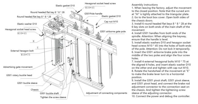
Pole Assembly Instructions
- Before leaving factory, movement is adjusted to closed position. Ensure curved arm at "M" is tightly attached to triangular plate.
- Remove chassis lid and open both sides of chassis doors.
- Install 6 round head flat keys 8×8×28 at the 6 key slots on both ends of main shaft.
- Install G501 handles from both ends of spindle. When aligning keyway, ensure handle is level.
- Install elastic washers D10 and hexagon socket head screws M10×45 into holes of both pole ends. Do not lock temporarily.
- Insert G501 airborne brake pole between two poles and align four screw holes.
- Install 4 external hexagonal bolts M10×75 at aligned holes, insert elastic washer D10 on other end and tighten with cap nut M10.
- Rotate handwheel at "E" to position brake lever horizontally.
- Install G501 pivot shaft, pivot sleeve, and pivot head, connecting brake rod adjustment connector to chassis connection seat. Tighten adjusting connector screw sleeve.
- Connect power and debug controller.
Similar Products

Get in Touch
Have questions about our products or want to discuss a custom order? Our team is ready to help you.
Company
SHENZHEN SINOMATIC TECHNOLOGY CO., LIMITED
Location
3F, Bldg B, No. 55 Langbei Vlg, Tongde Community, Baolong, Longgang, Shenzhen, 518116, China.
Contact Person
Manfrid Lee