
Easy Assembly Common Anode 7 Segment Display 1.2 Inch InGaN Chip Light Weight
Costomized 3.45mm (1.2") 5×7 Ultra Yellow Green Dot Matrix LED Displays Manufacturer
- Features:
- 1.2inch (30.0mm) Matrix height.
- Colors: Ultra White
- Flat package and light weight.
- Easy assembly.
- High quality and low cost.
- High reliable and intensity.
- Low power requirement.
- The product itself will remain within RoHS compliant version.
- Descriptions:
- The DL-S34571 series is a large emitting area (3.0mm diameter) LED sources configured in a 35 dots 5*7 matrix array.
- These displays provide excellent reliability in bright ambient light.
- These devices are made with white dots and black surface.
- Applications:
- Audio equipment.
- Instrument panels.
- Digital read out display.
- We promise:
- Your inquiry be replied in shortest time, no more than 12 hours
- 15 years of experience in LED and 7 segment LED display industry
- Good after-service
- Prompt delivery time
- OEM/ODM orders are accepted
- For OEM orders
- Usually, we make samples free for customers, while customers afford shipping charge of samples
- If sample need new mold, customers will afford the mold charge
- For ODM orders:
- We have an experienced designer and technician team to develop new products according to customer's demands
- We provide with various solutions
- Providing you with the best service is our mission
- Sizes:
- Digit size: 14.20mm (0.56 inches)
- Outer size: 25 x 19 x 8mm
Device Selection Guide:
| Model No. | Chip Material | Source Color | Description |
|
DL-S34571AYGB-S |
InGaN |
Black |
Row Anode |
|
DL-S34571CYGB-S |
Black |
Row Cathode |
- Absolute Maximum Ratings at Ta=25℃
|
Power Dissipation Per Segment |
PD | 90 | mW |
|
Peak Forward Current (Per Segment) |
IFP | 100 | mA |
| Forward Current (Per Segment) | IF | 25 | mA |
| Dating Linear From 50℃ | 0.4 | mA/℃ | |
| Reverse Voltage | VR | 5 | V |
| Operating Temperature Range | Topr | -40℃ to +80℃ | |
| Storage Temperature Range | Tstg | -40℃ to +85℃ | |
| Soldering Temperature | Tsld | 260℃ for 5 Seconds | |
Electrical Optical Characteristics at Ta=25℃
| Parameters | Symbol | Min. | Typ. | Max. | Unit | Test Condition |
| Luminous Intensity | IV | 70.0 | 130.0 | --- | mcd | IF=20mA (Note 1) |
| Luminous Intensity Matching Ratio (Segment To Segment) | Iv-m | --- | --- | 2:1 | IF=10mA | |
| Chromaticty Coordinates | X | --- | 0.30 | --- | nm | IF=20mA |
| Y | --- | 0.31 | --- | nm | IF=20mA (Note 2) | |
| Forward Voltage | VF | --- | 3.3 | 4.00 | V | IF=20mA |
| Reverse Current | IR | --- | --- | 50 | µA | VR=5V |
Notes:
- Luminous intensity is measured with a light sensor and filter combination that approximates the CIE eye-response curve.
- The dominant wavelength (λd) is derived from the CIE chromaticity diagram and represents the single wavelength which defines the color of the device.
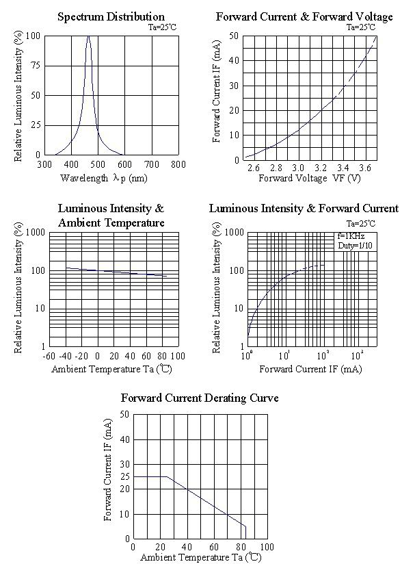
- Typical Electrical / Optical Characteristics Curves
- Please read the following notes before using the datasheets:
1. Over-current-proof
Customer must apply resistors for protection, otherwise slight voltage shift will
cause big current change ( Burn out will happen ).
2. Storage
2.1 Do not open moisture proof bag before the products are ready to use.
2.2 Before opening the package, the LEDs should be kept at 30℃ or less and 90%RH or less.
2.3 The LEDs should be used within a year.
2.4 After opening the package, the LEDs should be kept at 30℃ or less and 70%RH or less.
3. Soldering Condition
3.1 Pb-free solder temperature profile.
3.2 Reflow soldering should not be done more than two times.
4. Soldering Iron
Each terminal is to go to the tip of soldering iron temperature less than 260℃ for 5 seconds
within once in less than the soldering iron capacity 25W. Leave two seconds and more
intervals, and do soldering of each terminal. Be careful because the
damage of the product is often started at the time of the hand solder.
5. Repairing
Repair should not be done after the LEDs have been soldered. When repairing is unavoidable,
a double-head soldering iron should be used. It should be confirmed beforehand whether the characteristics of the LEDs will or will not be damaged by repairing.
Get in Touch
Have questions about our products or want to discuss a custom order? Our team is ready to help you.