
150–350 mm Ship Cross Bitt Bollard | GB 10106-88 Type A/B for Ship Mooring
150–350 mm Ship Cross Bitt Bollard | GB 10106-88 Type A/B for Ship Mooring
Product Overview
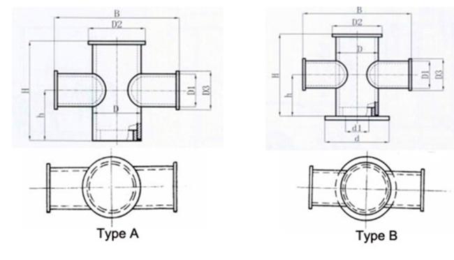
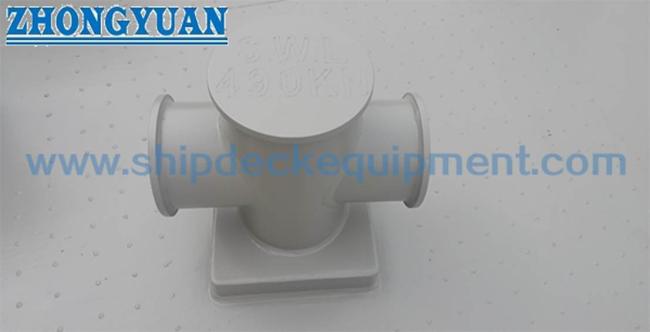
The GB 10106-88 ship cross bitt is a welded deck mooring fitting used to secure shipboard mooring lines. Its cruciform arrangement combines a vertical bitt with a transverse cross bar, providing practical rope wrapping and securing positions within a compact deck area.
The standard series covers nominal diameters from 150 to 350 mm and includes Type A and Type B installation arrangements. Type A is directly welded to the ship deck, while Type B is welded to a deck liner. The two types should therefore be selected according to the vessel structural drawing and shipyard installation arrangement rather than treated as different load grades. The supplied GB 10106-88 table also provides reference rope sizes and the maximum breaking load of the applicable wire rope; these rope values are not the SWL or breaking load of the cross bitt.
Quick Specifications
- Product type: Ship Cross Bitt / Cruciform Mooring Bollard → welded deck fitting for securing ship mooring lines.
- Standard and type: GB 10106-88 Type A / Type B → two installation arrangements within the same cross-bitt size series.
- Nominal diameter: 150–350 mm → five sizes for matching the vessel mooring arrangement, rope size, and installation drawing.
- Applicable wire-rope maximum breaking load: 117–686 kN → rope-selection reference from the supplied table; not bollard SWL.
- Applicable rope types: Steel wire rope / synthetic fiber rope / Malina rope → reference diameters vary with nominal bitt size.
- Installation: Type A direct deck weld / Type B deck-liner weld → select according to vessel structural details.
- Reference weight: 31–204 kg → varies with nominal size and Type A / Type B arrangement.
- Construction and finish: Welded steel structure with project-specific marine coating → final material, WPS, coating, and inspection scope to be confirmed.
Main Technical Parameters
Main selection data from the supplied GB 10106-88 table. Dimensions are in mm unless otherwise stated. The load column is the maximum breaking load of the applicable wire rope and must not be read as cross-bitt SWL.
|
Nominal |
Applicable Wire Rope |
Steel Wire |
Synthetic Fiber |
Malina Rope |
H |
Type A |
Type B |
|---|---|---|---|---|---|---|---|
| 150 | 117 (12) | 13 | 30 | 44 | 480 | 31 | 33 |
| 200 | 225 (26)* | 19.5 | 45 | 64 | 560 | 62 | 66 |
| 250 | 382 (39) | 26 | 56 | 80 | 640 | 98 | 105 |
| 300 | 549 (56) | 30 | 70 | 104 | 680 | 143 | 153 |
| 350 | 686 (70) | 34.5 | 77 | 120 | 720 | 192 | 204 |
Type A / Type B Installation Difference
|
Type |
Installation Arrangement |
Selection Basis |
|---|---|---|
| Type A | Directly welded to the ship deck | Use when the vessel structural drawing specifies a direct deck-welded interface. |
| Type B | Welded to a deck liner | Use when the vessel structural drawing specifies a liner between the cross bitt and deck structure. |
Type B should not automatically be described as a higher-load version. Deck plate thickness, liner arrangement, local reinforcement, weld size and welding procedure should follow the vessel structural drawing and project requirements.
Selection & Inquiry Guide
Step 1: Confirm GB 10106-88 and the required nominal diameter 150 / 200 / 250 / 300 / 350 mm according to the vessel mooring arrangement and project drawing.
Step 2: Confirm mooring rope type, rope diameter and rope MBL. Use the standard rope data as a selection reference only; do not convert the rope breaking-load value directly into bollard SWL.
Step 3: Confirm Type A or Type B according to the installation drawing: direct deck welding for Type A or deck-liner installation for Type B.
Step 4: Confirm material grade, fabrication requirement, WPS / welding requirement and surface-treatment system. Stainless steel or special material is subject to project confirmation.
Step 5: Confirm deck structure, liner arrangement where applicable, local reinforcement, weld detail and classification-society inspection requirement with the shipyard or vessel designer.
Step 6: Provide quantity, vessel type, installation position, replacement drawing or photo if available, delivery destination and required delivery time.
Structure
Vertical steel bitt | Transverse cross bar | Welded cruciform structure | Type A direct-deck interface or Type B deck-liner interface | Rope-contact surfaces | Specified marine coating
Fabrication, Installation & Engineering Advantages
- The cruciform arrangement provides multiple practical rope wrapping and securing positions around the vertical post and transverse cross bar.
- The 150–350 mm standard range supports selection by vessel drawing, rope diameter and the applicable rope load data stated in the standard table.
- Type A and Type B provide different installation interfaces while retaining the same basic cross-bitt mooring function.
- Fabrication accuracy of the vertical bitt, cross bar and deck interface is important for dimensional fit-up and shipyard welding.
- Rope-contact surfaces should be smooth and free from harmful sharp edges that could cause localized wear to steel wire or fiber mooring ropes.
- The deck plate, liner and local reinforcement remain part of the vessel structural design and should be checked independently from the rope-selection table.
- For replacement projects, existing foundation dimensions, deck thickness, liner arrangement, weld details and rope lead should be checked before production.
Custom Attributes
- Standard: GB 10106-88 → governing basis for the Type A / Type B dimensions and rope-selection data used on this page.
- Type: A / B → Type A is directly welded to the deck; Type B is welded to a deck liner.
- Nominal Diameter: 150 / 200 / 250 / 300 / 350 mm → select according to vessel drawing, rope data and installation arrangement.
- Applicable Rope: Steel wire / synthetic fiber / Malina rope → confirm rope diameter and MBL before quotation.
- Material: Project-specified steel → exact grade and any stainless-steel alternative should be confirmed before production.
- Installation: Welded → deck structure, liner, reinforcement and weld details follow the vessel structural design.
- Surface Treatment: Project-specific marine coating → blasting, primer and final coating system should follow vessel or owner specification.
- Certificate Requirement: According to project scope → material documentation, maker certificate and class inspection to be confirmed before order.
How It Works
Mooring line approaches the cross bitt → Rope is led around the vertical post and transverse cross bar → Required turns secure the mooring line → Mooring force is transferred through the welded cross-bitt structure → Load is introduced into the deck or deck-liner structure according to the vessel installation design
Applications
Cargo vessels | Tankers | Workboats | Tugboats | Barges | General ship deck mooring stations | Newbuilding projects | Replacement of legacy GB 10106-88 cross bitts
Certifications & Advantages
Certificates and inspection documentation can be arranged according to project requirement, material traceability, order scope, and classification-society approval procedure.
Certification: CCS, NK, BV, ABS, DNV, LR, KR, IRS, RS, RINA, CRS, Makers Test Certificate.
Drawing & Photos

FAQ
Q1: What is the difference between Type A and Type B cross bitts?
A1: Type A is designed for direct welding to the ship deck, while Type B is welded to a deck liner. The difference is primarily the installation arrangement. Type B should not automatically be considered a higher-load version.
Q2: Does the 117–686 kN value represent the SWL of the cross bitt?
A2: No. The GB 10106-88 table identifies these values as the maximum breaking load of the applicable wire rope. They are rope-selection reference values and must not be used directly as the bollard SWL, permissible load, or bollard breaking load.
Q3: How should the correct cross bitt size and type be selected?
A3: Confirm the vessel mooring arrangement, rope type, rope diameter and MBL first, then select the corresponding nominal bitt size and Type A or Type B installation arrangement. Deck structure, liner, local reinforcement and welding details should be checked against the vessel drawing before production.
Get in Touch
Have questions about our products or want to discuss a custom order? Our team is ready to help you.