
EDAN F2 Fetal Patient Monitor Parts Display Board Panel 21.53.114327-1.0.2C E204460
EDAN F2 Fetal Patient Monitor Parts Display Board Panel 21.53.114327-1.0.2C E204460
Product Description
This display board, model 21.53.114327-1.0.2C / E204460, is a display driver component for the monitor and is specifically designed for the F2 model. It features a green, high-density PCB design, integrating the LCD screen driver chip, backlight control circuit, signal processing module, and multiple interfaces (including pin header interfaces on the top, power terminals on the right, and screen cable interfaces on the bottom), with a compact layout and robust protection. It is responsible for receiving, processing, and driving the display of critical monitoring information such as fetal heart rate, uterine contractions, and fetal movement. It is a key component for resolving issues such as screen flickering, black screens, and backlight failure when repairing the F2 monitor.
Main functions
1. Signal Processing and Driving: Receives image and data signals from the motherboard, filters, stabilizes, and encodes them, then precisely drives the LCD screen to display fetal heart rate waveforms, uterine contraction curves, fetal movement counts, and various monitoring parameters, ensuring clear and smooth visuals.
2. Backlight Control and Adjustment: Built-in backlight driver circuitry allows for flexible adjustment of screen brightness according to the clinical environment, ensuring clear readability in low-light conditions while avoiding strong light that could irritate the mother or interfere with medical procedures.
3. Display Stability Guarantee: Anti-interference circuitry and signal verification mechanisms filter electromagnetic interference in the clinical environment, preventing screen flickering, jitter, distortion, or afterimages, ensuring the continuity and accuracy of monitoring information.
4. System Collaboration and Interaction: Deeply integrated with the overall system, supporting real-time updates of monitoring data, interface switching, alarm information pop-ups, and other functions, ensuring that the displayed content is synchronized with the device's operating status.
Steps for Removing the Display Board
1.Separate the upper and lower assemblies of the monitor.
2.Disconnect the five wires from the power inverter board, main control board, and touch screen controlling board (marked with arrows).
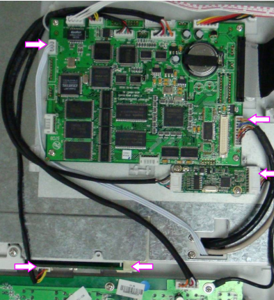
3.Remove the four screws indicated by arrows.
4.Place the upper assembly upright and fully open the display assembly.
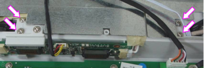
5.Unscrew the four screws that fix the display board to the display assembly stander, then carefully take off the display board.
Installation Precautions
- Power Off First: Before disassembly or assembly, the device power must be turned off, the power cord unplugged, and the battery removed. Never plug or unplug interfaces or touch components on the board while it is powered on to prevent short circuits and damage to the display board or motherboard.
- When plugging or unplugging the ribbon cable, hold the connector body firmly and apply force smoothly. Never pull the cable directly. Pay attention to the interface orientation during installation; never force it in the wrong direction to avoid damaging the pins or the ribbon cable.
Get in Touch
Have questions about our products or want to discuss a custom order? Our team is ready to help you.