
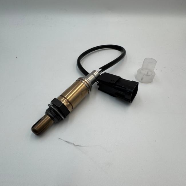
Car Upstream Downstream O2 Sensor 0258005133 For AvtoVAZ Chevrolet Niva Alfa Romeo
| Specification | Details |
|---|---|
| Product Type | Lambda Sensor (Oxygen / O2 Sensor) |
| OE Part Number | 0 258 005 133 |
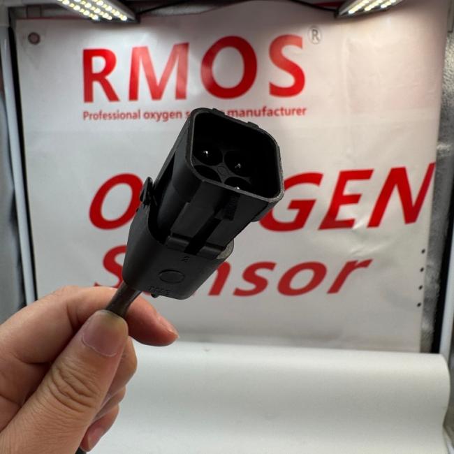
| Number of Circuits / Wires | 4 |
| Overall Length | 440 mm |
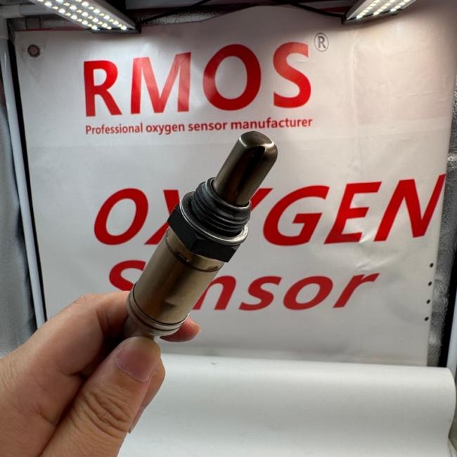
| Thread Size | M18 × 1.5-6e |
| Spanner Size | 22 mm (7/8″) |
| Fitting Position | Before Catalytic Converter (Upstream / Pre‑Catalyst) |
| Recommended Replacement Interval | 160,000 km (100,000 miles) |
Technical Notes:
-
This is a 4‑wire heated zirconium oxide oxygen sensor. The four wires provide two independent circuits – two for the internal heater (power and ground) and two for the sensor signal and ground.
-
The built‑in heating element brings the ceramic sensing tip up to operating temperature quickly after a cold start, enabling the ECU to enter closed‑loop fuel control sooner and significantly reduce cold‑start emissions.
-
Under rich (excess fuel) conditions, the sensor generates a voltage output of approximately 0.6 – 1.0 V. Under lean (excess oxygen) conditions, the voltage falls to near 0 V. The ECU uses this feedback to continuously adjust fuel delivery for optimal combustion efficiency.
-
The sensor is constructed with a stainless‑steel shell that resists rusting and provides greater dependability. The centre ceramic element is composed of Zirconium Oxide, Alumina and Yttrium Oxide, with platinum applied using vapour deposition to ensure even application. A spinel coating on the outer platinum layer prevents solid particles in the exhaust gas from damaging the component.
-
All sensors undergo 100% testing to meet or exceed original equipment quality standards.
The following OEM and aftermarket part numbers are known to be cross‑referenced with this sensor. Always verify physical fitment (connector shape, cable length and thread size) with your original part before purchasing.
| Manufacturer / Brand | Cross‑Reference Number(s) |
|---|---|
| AC Delco | AC97 (original equipment on early Lada Niva models) |
| 0 258 005 133 | |
| FISPA | 90055 (for Fiat/Alfa Romeo applications) |
| Intermotor | 64139 |
| NTY | ESL-CH-005, ESL-SU-005 |
| QH | XLOS104 |
Lada / VAZ / ZAZ OEM Numbers:
-
2108, 2109, 2110, 2111, 2112, 2113, 2114, 2115, 2120, 2123, 2131
-
1.3L–1.7L engine variants
Additional Reference Numbers:
-
Heater resistance: 4 Ω (some aftermarket variants have this specification)
-
Zirconia type with insulated earth
Cross-Reference Notes:
-
The original AC97 AC Delco sensor is no longer in production and has been superseded by this part number as a direct functional replacement for Lada Niva and other VAZ applications.
-
This sensor is listed as compatible with 4‑wire zirconium oxide lambda sensor applications for 1.3L–1.7L VAZ engines.
-
Always physically compare your old sensor’s connector shape, pin count, cable length (440 mm) and thread size (M18 × 1.5) before purchasing. Aftermarket versions may have slight variations in connector design or calibration parameters.
This Lambda Sensor is primarily used as an upstream (pre‑catalyst) regulating probe in vehicles from the Russian automotive group AvtoVAZ, marketed under the LADA brand, as well as ZAZ, VAZ and Chevrolet Niva models. It is also compatible with certain Fiat, Alfa Romeo and Fiat Panda applications.
The following models originally fitted with this sensor under part number 0 258 005 133:
| Model | Model Code | Year Range | Engine / Notes |
|---|---|---|---|
| 110 | 2110 | 1995 – 2005 | 1.5L / 1.6L petrol – Upstream position |
| 111 | 2111 | 1996 – 2005 | 1.5L / 1.6L petrol – Upstream position |
| 112 | 2112 | 2000 – 2005 | 1.5L / 1.6L petrol – Upstream position |
| Niva / Niva Closed Off-Road Vehicle | 2121, 2123, 2131 | 1996 – 2006 | 1.7L petrol (59 kW / 80 PS) – Upstream position |
| Samara / Sputnik | 2108, 2109, 21099, 2113, 2114, 2115 | 1994 – 2013 | 1.3L, 1.5L petrol – Upstream position |
| Kalina | 1117, 1118, 1119 | 2004 – 2009 | 1.6L 8V/16V petrol – Upstream regulating probe (Euro‑2/3) |
| Priora | 2170, 2171, 2172 | 2007 – 2010 | 1.6L 16V petrol – Upstream position |
| Granta | 2190 | 2011 – 2013 | 1.6L petrol – Upstream position |
| 2111 / 2115 | VAZ‑2111, VAZ‑2115 | Various | 1.5L / 1.6L petrol |
| Model | Notes |
|---|---|
| BA3 (Lanos) | Compatible with 1.3L–1.7L petrol engines |
| Slavuta, Tavria, Vida | Petrol engine variants that share VAZ powertrain components |
| Model | Year Range | Engine / Notes |
|---|---|---|
| Niva / Chevrolet Niva | 2003 – 2020 | 1.7L 4x4 petrol – Upstream position (regulating sensor) |
| Niva (UK market, single‑point injection) | 1995 – 1998 | 1.7L – The ECU on these vehicles suffers from a known ground signal issue with aftermarket sensors |
| Chevrolet Lanos | Various | 1.3L–1.7L petrol – Upstream sensor |
| Model Code | Vehicle Name | Compatible Engine Capacity |
|---|---|---|
| VAZ‑2108 | Samara (hatchback) | 1.3L, 1.5L |
| VAZ‑2109 | Samara (5‑door) | 1.3L, 1.5L |
| VAZ‑21099 | Samara (saloon) | 1.5L |
| VAZ‑2110 | Lada 110 | 1.5L, 1.6L |
| VAZ‑2111 | Lada 111 (estate) | 1.5L, 1.6L |
| VAZ‑2112 | Lada 112 (hatchback) | 1.5L, 1.6L |
| VAZ‑2113 | Samara (restyled) | 1.5L |
| VAZ‑2114 | Samara (restyled, 5‑door) | 1.5L |
| VAZ‑2115 | Samara (restyled, saloon) | 1.5L |
| VAZ‑2120 | Niva (5‑door, VAZ‑2120) | 1.7L |
| VAZ‑2121 | Niva (3‑door) | 1.7L |
| VAZ‑2123 | Chevrolet Niva | 1.7L |
| VAZ‑2131 | Niva (5‑door extended) | 1.7L |
| ZAZ BA3 | ZAZ Lanos | 1.3L, 1.4L, 1.5L, 1.6L |
| Make | Model | Engine / Notes |
|---|---|---|
| Fiat | Brava, Bravo, Doblo, Ducato, Marea, Multipla, Palio, Punto, Scudo, Stilo | Selected 1.6L, 1.8L, 2.0L petrol engines |
| Alfa Romeo | 156, 166, GT, GTV, Spider | Selected petrol engines |
| Lancia | Thesis, Lybra | Selected petrol engines |
| Fiat Panda | 141 (1996–2000) | 1.1L / 1.2L petrol – Upstream sensor |
Fitment Notes:
-
This is an upstream (pre‑catalyst / front) oxygen sensor for the vast majority of applications listed above. It is installed before the catalytic converter and serves as the primary regulating probe that directly influences the ECU‘s fuel trim adjustments.
-
Upstream and downstream O₂ sensors are not interchangeable in most vehicles. Replacing an upstream sensor with a downstream unit (or vice versa) will result in improper ECU readings and persistent fault codes.
-
For most 4‑cylinder LADA / VAZ vehicles, there are typically two oxygen sensors: upstream (pre‑cat / regulating) and downstream (post‑cat / diagnostic). This part is for the upstream position.
-
For later Euro‑3+ vehicles, the downstream (diagnostic) sensor generally uses a different part number.
-
Not compatible with diesel engines – diesel O₂ sensors use different calibration parameters and part numbers.
-
The vehicle fitment information above is a guide only. Always confirm compatibility using your vehicle’s VIN, or by physically inspecting your old sensor‘s part number and connector shape before purchasing.
A faulty lambda sensor degrades the ECU‘s ability to accurately monitor the air‑fuel mixture. While the engine may still run, fuel economy, emissions and OBD‑II readiness are negatively affected. Replace your lambda sensor immediately if you experience any of the following symptoms.
| Symptom Category | Specific Indicators |
|---|---|
| Check Engine Light (MIL) Illumination | – The dashboard MIL illuminates, often without any immediate drivability change. – Error code 13 (lambda probe signal anomaly) is recorded by the on‑board diagnostic system. This is a known issue when using aftermarket sensors on some Lada Niva models due to ECU grounding design. – Common OBD‑II fault codes include: • P0130 – P0135 – Front oxygen sensor circuit / heater range / performance malfunction • P0030 – P0037 – Heater circuit control circuit (Bank 1, Sensor 1) • P0133 – O₂ Sensor Circuit Slow Response (upstream) • P0420 – Catalyst System Efficiency Below Threshold (Bank 1) |
| Increased Fuel Consumption | – The ECU defaults to preset rich parameters when sensor feedback is missing. A faulty lambda sensor can increase fuel consumption by 10–15% or more as the engine management system enters failsafe mode. |
| Poor Engine Performance / Driveability | – Hesitation or stumbling during acceleration – particularly noticeable when overtaking or pulling away from junctions. – Noticeable lack of power under load (e.g., uphill driving or towing). – Sluggish throttle response – the engine feels unresponsive or “heavy”. – Engine may feel “flat” at certain throttle positions. |
| Rough Idle & Stalling | – The engine runs unevenly at low speeds (“hunting” or “lumpy” idle). – Fluctuating idle speed. – Stalling when coming to a stop at traffic lights or junctions. |
| Cold‑Start Difficulty | – Extended cranking time required to start a cold engine. – Fluctuating or unstable idle immediately after cold start, until the engine warms up. – The ECU may remain in open‑loop mode longer than intended. |
| Exhaust & Emissions Symptoms | – Black smoke from the exhaust – indicates an excessively rich air‑fuel mixture and incomplete combustion. – Strong smell of unburnt fuel in the exhaust stream. – Failed emissions test (smog check) – incorrect sensor readings prevent the ECU from maintaining correct air‑fuel ratio, causing a fail. – Rotten‑egg (sulphur) odour – a rich‑running condition that can damage the catalytic converter over time. – Soot‑covered spark plugs – may lead to misfires. |
| OBD‑II Readiness Monitors Not Set | – The oxygen sensor and catalyst monitors remain “Not Ready,” blocking an emissions inspection pass. – The vehicle fails the drive cycle requirement. |
Potential Causes of Sensor Failure:
-
Normal wear and tear – Lambda sensors typically degrade after 100,000 – 160,000 km (60,000 – 100,000 miles) of operation due to continuous exposure to high‑temperature exhaust gases (up to 930 °C) and thermal cycling stress.
-
Contamination (“sensor poisoning”) – Oil, coolant, silicone‑based sealants, or the use of leaded fuel permanently coats the ceramic sensing tip, destroying its ability to detect oxygen. The use of fuel containing lead or silicon impurities accelerates sensor failure.
-
Heater circuit failure – The internal heating element opens or shorts. Heater resistance should be approximately 4 Ω at room temperature for this model; an open circuit (infinite resistance) or short circuit (0 Ω) indicates failure.
-
Physical impact damage – Dropping the sensor or impact from road debris can crack the fragile ceramic element.
-
Wiring / connector issues – Damaged wiring, loose connections, corrosion at the connector, or an intermittent open / short circuit can trigger fault codes even when the sensor itself is healthy.
-
Exhaust leaks upstream of the sensor – False oxygen readings from an upstream exhaust leak (cracked manifold, failed gasket, etc.) will cause erratic sensor output and may be incorrectly attributed to a faulty sensor.
Diagnostic Tips:
-
A failing lambda sensor frequently triggers the MIL without any noticeable drivability change initially. Fuel consumption, however, is still negatively affected.
-
On Lada Niva vehicles with single‑point injection (UK market, 1995–1998), a known design flaw with the ECU means that aftermarket sensors may result in Error code 13 (lambda probe signal anomaly) even when the sensor is brand new. This is not a sensor defect – it is due to the ECU‘s lack of a proper signal ground reference. The solution is to cut and join the wires leading to terminals D6 and A11 in the ECU harness to restore correct operation.
-
To diagnose a faulty sensor:
-
Heater circuit test: Use a digital multimeter to measure the resistance across the heater circuit. A healthy sensor should read approximately 4 Ω at room temperature. An open circuit (infinite resistance) or short circuit (0 Ω) indicates failure.
-
Sensor signal test: Use an OBD‑II scanner or oscilloscope to monitor the sensor voltage output under steady‑state driving. A healthy narrow‑band upstream sensor fluctuates continuously between approximately 0.1 V – 0.9 V (typically oscillating several times per second). If the voltage remains steady (stuck high, stuck low, or at a fixed mid‑range value), does not fluctuate, or changes very slowly, the sensor is failing.
-
-
P0420 can be caused by a failing downstream oxygen sensor, a failing catalytic converter, or an upstream sensor that is no longer providing accurate readings to the ECU.
-
Always investigate the root cause before replacing the sensor – if contamination (oil, coolant, silicone) caused the failure, replacing the sensor without addressing the underlying issue will result in repeated premature failure.
1. Confirm Fitment – Physical Inspection is Essential
-
This is a direct‑fit sensor with a 4‑pin connector (not a universal splice‑in sensor), M18 × 1.5 thread, and 440 mm overall length.
-
Do not purchase based solely on the OE number – aftermarket manufacturers may produce sensors with the same OE reference but with slight differences in cable length, connector shape or calibration parameters. If the connector does not match, do not install.
-
Physical inspection of your original sensor is strongly recommended. Compare the connector shape, pin count, cable length (440 mm) and thread size (M18 × 1.5) before ordering.
2. Verify Sensor Position – Upstream (Pre‑Catalyst)
-
This sensor is designed for the upstream (pre‑catalyst / front) position for the majority of applications listed above.
-
Upstream and downstream O₂ sensors are not interchangeable in most vehicles. Replacing an upstream sensor with a downstream unit (or vice versa) will result in improper ECU readings and persistent fault codes.
-
For most 4‑cylinder LADA / VAZ vehicles, there are two oxygen sensors: upstream (pre‑cat / regulating) and downstream (post‑cat / diagnostic). This part is for the upstream position.
-
If your original sensor is located after the catalytic converter, a different part number may be required. Verify the position of your old sensor before ordering.
3. Replacement Interval
-
Lambda sensors degrade gradually over time, often without triggering immediate fault codes. Their switching response becomes slower and their voltage range narrows with age and mileage.
-
Replacement at the manufacturer‑recommended interval of 160,000 km (approx. 100,000 miles) is recommended to maintain optimal fuel efficiency, catalytic converter health, proper emissions output and correct OBD‑II monitor readiness.
-
Even if no Check Engine Light is present, an aged sensor will still respond more slowly than a new one, negatively affecting fuel economy and emissions. Proactive replacement can save up to 15% on fuel consumption.
4. Lada Niva ECU Grounding Issue – Special Consideration
-
Important: On Lada Niva vehicles with single‑point / throttle‑body fuel injection (UK market 1995–1998), a known design flaw with the ECU means that aftermarket sensors may result in Error code 13 (lambda probe signal anomaly) even with a brand new sensor.
-
Cause: The original AC97 sensor shares a signal ground between terminal C and the sensor body. Most aftermarket sensors (including this one) have the sensor ground isolated from the case, leaving the circuit “floating” without a proper ground path.
-
Solution: A wiring modification can be performed. All that needs to be done is that a couple of wires need to be cut and spliced together. The wires leading to terminals D6 and A11 should be carefully cut and joined together. This should then restore correct operation of the emission control system even with an aftermarket oxygen sensor.
-
Disclaimer: This modification relates to vehicles fitted with the single‑point / throttle‑body fuel injection system as fitted to Nivas in the UK between 1995 and 1998. The installer should disconnect the vehicle battery before this work is undertaken, and the ECU unplugged.
5. Installation Tips
Before Installation:
-
Allow the exhaust system to cool completely before removal – the exhaust manifold and catalytic converter remain dangerously hot for a significant period after engine shutdown (up to 30 minutes).
-
Disconnect the vehicle‘s battery negative (-) cable before starting work to prevent electrical issues, potential ECU damage, or accidental short circuits.
-
Use a high‑quality O₂ sensor socket (22 mm / 7/8″) with an offset design to prevent stripping the sensor‘s flats and to provide better access in confined engine bays. A standard deep socket can easily damage the sensor housing or its flats.
Removal of the Old Sensor:
-
Apply penetrating oil to the threads of the old sensor the night before removal to ease extraction.
-
If the sensor is difficult to remove when cold, it may be easier when the exhaust is warm (run the engine for 1‑2 minutes, then allow it to cool until it is warm but not scalding). Exercise extreme caution to avoid burns – wear heavy‑duty work gloves.
-
Do not use excessive force – damage to the exhaust bung threads can result in expensive repairs and potentially require exhaust component replacement or thread repair.
-
Disconnect the electrical connector carefully – press the locking tab and pull only the connector housing (never pull directly on the wires).
-
Inspect the old sensor‘s connector, cable and tip for signs of contamination (oil, soot, coolant residue), melting or cracking. Note any contamination – this indicates an underlying engine issue that must be addressed before installing the new sensor.
Installation of the New Sensor:
-
Do not apply additional anti‑seize compound unless the new sensor‘s threads are completely dry. Many sensors are factory‑coated with anti‑seize. Adding extra can contaminate the sensor tip and cause premature failure. If the threads are dry, apply a small amount of sensor‑safe anti‑seize compound to the threads only – never to the sensor tip.
-
Do not use silicone sealants anywhere near the exhaust system – silicone vapour will permanently contaminate and destroy the oxygen sensor (this is one of the most common causes of premature failure).
-
Avoid touching the sensor tip – skin oils contaminate the ceramic sensing element and cause inaccurate readings and premature failure. Always handle the sensor by the hexagon nut or connector body.
-
Do not drop the sensor – the ceramic element inside the metal housing is brittle and can crack upon impact, rendering the sensor inoperative even if no external damage is visible.
-
Tighten to the correct torque – typical torque for an M18 × 1.5 oxygen sensor is 40 – 50 Nm (30 – 37 ft‑lb) . Use a torque wrench to avoid overtightening.
-
CAUTION: Overtightening can damage threads in the exhaust bung and may crack the sensor housing. Undertightening may cause exhaust leaks and false oxygen readings.
-
-
Route the wiring harness securely using the original clips and routing guides to prevent contact with hot exhaust components (exhaust manifold, catalytic converter, EGR pipes) or moving parts (drive shafts, steering components, cooling fans).
-
Reconnect the electrical connector fully – an audible click confirms correct engagement. Ensure the locking tab is fully seated.
-
Reconnect the vehicle‘s battery after installation is complete.
Post‑Installation:
-
Start the engine and allow it to reach normal operating temperature (closed‑loop mode).
-
Verify that no exhaust gas leakage exists around the sensor bung (listen for “puffing” sounds or use a soap‑and‑water solution sprayed around the threads – bubbles indicate a leak).
-
Use an OBD‑II scanner to clear any existing fault codes.
-
Drive the vehicle through a complete drive cycle (typically 10‑20 minutes of mixed driving: stop‑start traffic, steady cruising and moderate acceleration) to allow the ECU to re‑learn adaptation values and complete oxygen sensor and catalyst monitors.
-
After the drive cycle, re‑scan for fault codes to confirm that the oxygen sensor monitors have completed and that no new codes have appeared.
6. Required Tools
| Tool | Purpose |
|---|---|
| O₂ sensor socket (22 mm / 7/8″) – offset type | Removal and installation of the sensor without damaging the flats or housing |
| Ratchet (3/8″ or 1/2″ drive) and extension bar (150–300 mm) | Access in confined engine bays (a longer extension is often required) |
| Torque wrench | To tighten the sensor to the correct specification (40 – 50 Nm / 30 – 37 ft‑lb) |
| Penetrating oil (e.g., WD‑40) | Apply to the old sensor‘s threads the night before removal to ease extraction |
| Anti‑seize compound (sensor‑safe) | ONLY required if the new sensor‘s threads are completely dry (check the manufacturer‘s instructions) |
| Jack and axle stands | If under‑vehicle access requires safe lifting – never rely on a jack alone |
| OBD‑II scanner | To clear fault codes, verify live sensor data, and check monitor readiness status |
| Digital multimeter | For testing heater resistance (approx. 4 Ω) and sensor voltage output if troubleshooting is needed |
7. Quantity Needed – Upstream Sensor
-
4‑cylinder LADA / VAZ petrol engines typically have two oxygen sensors: upstream (pre‑cat / regulating) and downstream (post‑cat / diagnostic). This part is for the upstream position.
-
For Euro‑2 vehicles, the downstream sensor may be absent – only one lambda sensor (upstream position) is fitted. This part is suitable for those vehicles.
-
For Euro‑3+ vehicles, the downstream (diagnostic) sensor uses a different part number – do not use this sensor in the downstream position.
-
If both upstream and downstream sensors are faulty, you will need the appropriate part numbers for each position.
8. Professional Installation Recommended
-
While this is a direct‑fit part, professional installation is strongly advisable if you are not experienced with exhaust system work or if the sensor is located in a difficult‑to‑reach position.
-
After replacement, the ECU may need to have adaptation values reset using manufacturer‑specific diagnostic equipment.
-
Improper installation can lead to:
-
Exhaust leaks around the sensor bung
-
Cross‑threaded or damaged exhaust bung threads – expensive to repair
-
Sensor damage from contamination or mishandling
-
Wiring damage from contact with hot exhaust components
-
Persistent ECU fault codes despite a correctly functioning sensor
-
-
If your vehicle has covered more than 100,000 km, it is common practice to replace the oxygen sensor proactively, even without fault codes, to restore fuel efficiency.
9. Warranty
-
OE‑manufactured sensors typically include a manufacturer warranty – commonly 1 year from the date of purchase.
-
Check with your specific retailer for their warranty terms and return policy.
-
Important: Most warranties are voided if the sensor tip shows contamination from improper handling (e.g., touching the tip, dropping the sensor, silicone exposure, or installation with contaminated hands / tools). Oxygen sensors are often non‑returnable except for approved warranty replacement due to contamination risk. Keep your original packaging until the new sensor is installed and confirmed working.
10. Common Mistakes to Avoid
| Mistake | Consequence |
|---|---|
| Adding extra anti‑seize compound (if the sensor is factory‑coated) | The compound contaminates the sensor tip, causing premature failure |
| Touching the sensor tip | Skin oils permanently contaminate the sensing element |
| Dropping the sensor (even from a low height) | The fragile ceramic element cracks; the sensor becomes inaccurate or completely inoperative |
| Using silicone sealants anywhere near the exhaust system | Silicone vapour permanently poisons the sensor – the part is ruined and cannot be repaired |
| Over‑tightening the sensor | Damaged exhaust bung threads; expensive exhaust repair or replacement |
| Under‑tightening the sensor | Exhaust leaks cause false oxygen readings and persistent fault codes |
| Installing the sensor in the wrong position (downstream instead of upstream) | The ECU receives incorrect data; persistent fault codes and poor fuel economy |
| Failing to clear fault codes after replacement | The ECU continues using old adaptation values; the MIL may remain illuminated |
| Ignoring wiring / connector problems | A new sensor can also appear faulty if the harness is damaged or corroded |
| Using the sensor with a damaged or mismatched connector | The sensor cannot communicate with the ECU; possible damage to the vehicle‘s wiring harness or ECU |
| Replacing only the sensor without diagnosing the cause of contamination | The new sensor will fail prematurely for the same reason (e.g., oil consumption, coolant leak) |
| Ignoring the known Lada Niva ECU ground issue | After replacement, Error code 13 appears despite a brand new sensor; perform the wiring modification |
Disclaimer: While we strive for accuracy, vehicle specifications and OE part numbers may vary by production date, market region and vehicle trim level. The vehicle fitment information provided for this part number is based on available cross‑reference data and is a guide only – not an exhaustive compatibility list. You should verify physical fitment (4‑pin connector, 440 mm cable length, M18 × 1.5 thread) and confirm the position (upstream / pre‑catalyst) of your old sensor before purchasing. This sensor is not compatible with diesel engines. For Lada Niva vehicles with single‑point fuel injection (UK market 1995–1998), a known ECU ground issue may require a wiring modification after installation – see Important Purchase Consideration #4 above. If your vehicle is not listed above, or if you are unsure of compatibility, consult your vehicle‘s manufacturer specifications, an authorised dealer or a qualified mechanic before ordering.
Get in Touch
Have questions about our products or want to discuss a custom order? Our team is ready to help you.