
Planar Probe Heated Auto Oxygen Sensor 55566648 For Gm Opel Saab Alfa Romeo Fiat Lancia Maserati
| Specification | Details |
|---|---|
| Product Type | Lambda Sensor (Oxygen / O2 Sensor) |
| OE Part Number | 55566648 |
| Sensor Type | Heated, Planar Probe Zirconium Oxide Type |
| Fitting Position | After Catalytic Converter (Downstream / Rear / Post-Catalyst) |
| Lambda Sensor Type | Diagnostic Probe (Catalyst Efficiency Monitor) |
| Heated | Yes |
| Number of Circuits / Poles | 4 |
| Connector Shape | Oval |
| Housing Colour | Black |
| Cable Length | 300 — 650 mm (Length varies by manufacturer; confirm fitment before purchase) |
| External Thread Size | M18 × 1.5 |
| Spanner Size | 22 mm (7/8″) |
| Quality Standard | OE Equivalent, 100% Tested |
| Recommended Replacement Interval | 100,000 — 160,000 km (60,000 — 100,000 miles) |
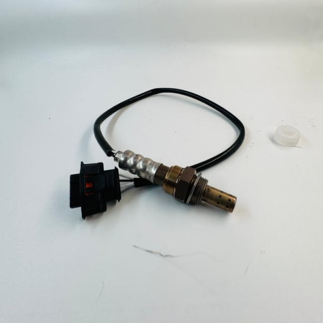
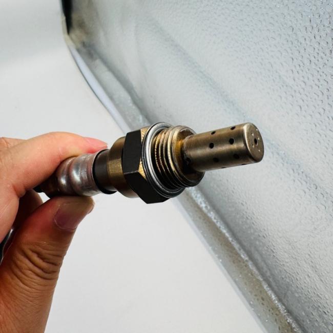
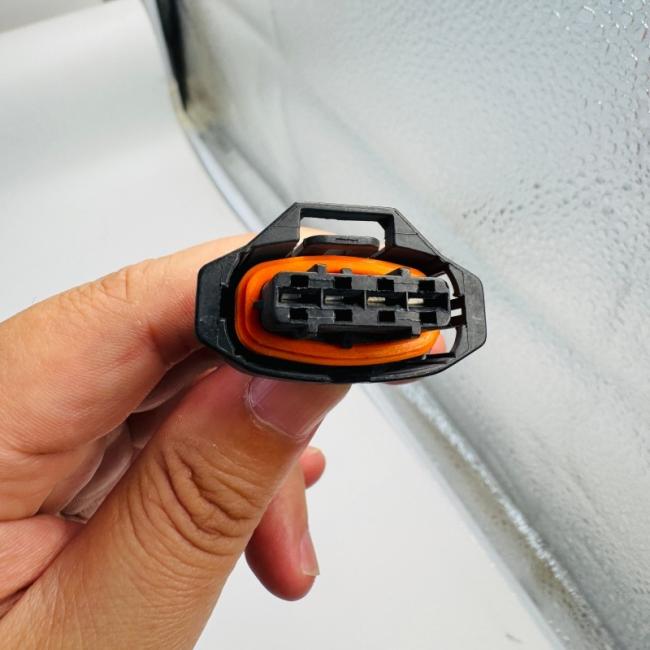
Technical Notes:
-
This is a 4-wire heated planar probe oxygen sensor. The planar design incorporates a thin, multi-layer ceramic substrate that provides faster light-off times and more precise measurement than traditional thimble-type designs.
-
The built‑in heating element brings the ceramic sensing tip up to operating temperature quickly after a cold start, enabling the ECU to enter closed‑loop fuel control sooner.
-
As a diagnostic probe (downstream sensor), this sensor is installed after the catalytic converter. Its primary function is to compare oxygen content in the exhaust gas exiting the catalyst against the upstream sensor reading. The ECU uses this differential to calculate catalytic converter efficiency. If the downstream sensor readings mirror those of the upstream sensor too closely, the ECU will flag a catalyst efficiency fault (P0420).
-
The sensor is constructed with a stainless-steel shell that resists rusting and provides greater durability under harsh exhaust environment conditions. The platinum coating on the ceramic element is applied using vapour deposition for even application, and a protective spinel coating helps prevent solid exhaust particles from damaging the component.
-
Critical safety note: This sensor is not a generic universal unit. It features a vehicle‑specific electrical connector designed for direct plug‑and‑play fitment and pre‑terminated wiring, eliminating the need for cutting or splicing during installation. If your replacement sensor does not have a matching connector, do not install it.
-
All sensors are 100% tested to meet or exceed original equipment quality standards. The threads are factory pre‑greased with anti‑seize compound to prevent seizing in the exhaust bung and to facilitate easier future removal.
Specifications compiled from multiple aftermarket catalogues including FAE, FISPA, Fuel Parts, Ridex, and Meat & Doria listings. Cable length specifications vary by manufacturer — always compare with your original sensor before purchasing.
The following part numbers are known cross‑references for this Lambda Sensor. This OE number is widely used across the GM Group. Always verify physical fitment (connector shape, cable length and thread size) with your original part before purchasing.
| Manufacturer | Cross‑Reference OE Number(s) |
|---|---|
| CHEVROLET / GM | 55566648, 55566650, 855356, 855357, 855358, 855422, 855426, 855553, 855554, 9202575, 9202576, 9202577, 93185456, 93185493, 9158718, 55205018, 55210300, 55353811, 55353812, 71744403, 71748280 |
| OPEL | 055566648, 055566650, 0855356, 0855357, 0855358, 0855422, 0855426, 0855553, 0855554, 09202575, 09202576, 09202577, 093185456, 093185493, 55566648, 55566650, 855356, 855357, 855358, 855422, 855426, 855553, 855554 |
| SAAB | 9202575, 93185456, 93185493 |
| ALFA ROMEO | 55205018, 55210300, 55353811, 55353812, 71744403, 71748280 |
| FIAT | 55205018, 55210300, 55353811, 55353812, 71744403, 71748280 |
| LANCIA | 55205018, 55210300, 55353811, 55353812, 71744403, 71748280 |
| MASERATI | 55210300 |
Cross-reference data compiled from Spareto, eBay, Buycarparts, Parts in Motion, and Ridex catalogues. Not all interchangeable numbers may be listed. Always verify fitment with your original sensor.
Important Cross-Reference Note:
-
It is critical to understand that 55566648 and 55566650 are not interchangeable in the same vehicle. These correspond to different positions on the exhaust system. Always confirm which position you are replacing before purchasing.
This Lambda Sensor is an original equipment component manufactured for the General Motors (GM) Group, widely used across Chevrolet, Opel, Vauxhall, Holden, Saab, Alfa Romeo, Fiat, and Lancia vehicles. The sensor is installed after the catalytic converter as a downstream (rear / post‑catalyst) diagnostic probe and is compatible with 1.4L — 2.4L 4‑cylinder petrol engines meeting Euro‑4 and Euro‑5 emissions standards.
⚠️ Critical Position Note: This sensor is for the downstream (post‑catalyst / rear) position (Bank 1, Sensor 2). It is not interchangeable with the upstream sensor (Bank 1, Sensor 1). The upstream sensor (typically part number 55566650 for these applications) requires a different part number. If your faulty sensor is located before the catalytic converter, this part is not correct for your vehicle.
| Model | Generation / Chassis | Year Range | Engine / Notes |
|---|---|---|---|
| Cruze | J300 (Saloon), J305 (Hatchback), J308 (Estate) | 2009 — 2016 | 1.4L / 1.6L / 1.8L petrol. Downstream (rear / post‑cat) position |
| Orlando | J309 (MPV) | 2011 — 2018 | 1.8L petrol. Downstream position |
| Excelle | (China market) | 2009 — 2017 | 1.6L / 1.8L petrol. Rear O₂ sensor |
| Model | Generation | Year Range | Engine / Notes |
|---|---|---|---|
| Excelle | (Chinese market) | 2009 — 2017 | 1.6L / 1.8L petrol. Downstream position |
| Model | Generation / Chassis | Year Range | Engine / Notes |
|---|---|---|---|
| Astra H | A04 (H) | 2004 — 2010 | 1.6L, 1.8L Z16XE / Z18XE petrol. Downstream (post‑cat) position |
| Astra J | P10 (J) | 2009 — 2015 | 1.4L, 1.6L, 1.8L petrol. Downstream position |
| Corsa D | S07 (D) | 2006 — 2014 | 1.4L, 1.6L petrol. Downstream position |
| Meriva B | S10 (B) | 2010 — 2017 | 1.4L / 1.6L petrol. Downstream position |
| Zafira B | (B) | 2005 — 2010 | 1.6L / 1.8L petrol. Downstream position |
| Insignia A | G09 (A) | 2008 — 2017 | Selected 1.6L / 1.8L petrol variants. Downstream position |
| Combo | C / D | 2001 — 2011 | 1.4L / 1.6L petrol. Downstream position |
| Model | Generation / Chassis | Year Range | Engine / Notes |
|---|---|---|---|
| Cruze | JG / JH | 2009 — 2016 | 1.8L petrol (F18D engine). Downstream (post‑cat) position |
| Cruze | JG Hatchback (JH Series II) | 2011 — 2016 | 1.4L / 1.8L petrol. Rear O₂ sensor |
| Brand | Model / Application | Notes |
|---|---|---|
| Alfa Romeo | 159 (939) Saloon / Sportwagon | 1.8L MPI petrol (2005‑2012, 140‑200 PS). Downstream position |
| Fiat | Selected 4‑cylinder petrol models | OE numbers 55205018, 55210300, 55353811, 55353812 cross‑reference |
| Lancia | Selected 4‑cylinder petrol models | OE numbers 55205018, 55210300, 55353811, 55353812 cross‑reference |
| Maserati | Selected models (OE 55210300) | Consult Maserati parts catalogue for specific model fitment |
| Saab | Selected 9‑3, 9‑5 petrol variants | OE numbers 9202575, 93185456, 93185493 cross‑reference |
Fitment Notes:
-
This is a downstream (post‑catalyst / rear) oxygen sensor. It is installed after the catalytic converter (Bank 1, Sensor 2) and serves as the diagnostic probe for catalyst efficiency monitoring.
-
Upstream and downstream O₂ sensors are not interchangeable in the same vehicle. For many applications listed (e.g., Chevrolet Cruze / Orlando / Excelle), the upstream sensor part number is 55566650, while this 55566648 is the downstream sensor.
-
For most 4‑cylinder vehicles listed above, there are two oxygen sensors: upstream (pre‑cat / regulating) and downstream (post‑cat / diagnostic). This part is for the downstream position.
-
Not compatible with diesel engines (pre‑Euro‑5 diesel engines generally do not use lambda sensors; newer diesel applications use different part numbers with different calibration parameters).
-
The vehicle fitment information above is a guide only. Always confirm compatibility using your vehicle‘s VIN, or by physically inspecting your old sensor‘s position (upstream vs. downstream), connector shape (oval), and cable length before purchasing.
-
Engine Compatibility Summary:
Engine Displacement Engine Codes Power Output 1.4L / 1.6L / 1.8L Z16XE, Z18XE, F18D, F16D3, F18D3, LDE, 1.8 MPI 109 — 141 HP 2.0L / 2.4L Selected variants (with downstream sensor fitment) 140 — 200 PS
Vehicle fitment information compiled from eBay listings, Spareto.com, Buycarparts.co.uk (FISPA 90186), and Ridex catalogues. Not all compatible vehicles may be listed. Always verify using your vehicle‘s VIN or original part number.
A faulty downstream lambda sensor degrades the ECU‘s ability to accurately monitor catalytic converter efficiency. While the engine may still run normally, emissions performance, fuel economy, and OBD‑II readiness are all negatively affected. Replace your lambda sensor immediately if you experience any of the following symptoms.
| Symptom Category | Specific Indicators |
|---|---|
| Check Engine Light (MIL) Illumination | – The MIL illuminates on the dashboard — often the first and only obvious symptom. – Common OBD‑II fault codes for a faulty downstream oxygen sensor include: • P0420 / P0430 – Catalyst System Efficiency Below Threshold (Bank 1 / Bank 2) — a failing downstream sensor can incorrectly indicate a bad catalytic converter • P0136 – P0141 – O₂ Sensor Circuit Malfunction / Heater Malfunction (Bank 1, Sensor 2) • P0036 – P0037 – HO₂S Heater Control Circuit (Bank 1, Sensor 2) • P0137 – O₂ Sensor Circuit Low Voltage (open circuit) • P0138 – O₂ Sensor Circuit High Voltage (short circuit) |
| Increased Fuel Consumption | – The ECU may indirectly affect fuel trim based on inaccurate downstream sensor signals. A faulty lambda sensor can increase fuel consumption by 10‑15% or more, leading to noticeably higher fuel bills without any change in driving style. |
| Poor Engine Performance / Driveability | – Hesitation, surging, or stumbling during acceleration — particularly noticeable when the vehicle is under load (e.g., uphill driving, overtaking, or towing). – Sluggish throttle response — the engine feels unresponsive or “heavy”. – Lack of power / reduced engine performance due to incorrect fuel mixture adjustments. |
| OBD‑II Readiness Monitors Not Set | – The oxygen sensor and catalyst monitors remain “Not Ready”, blocking an emissions inspection pass (smog test / MOT). – The vehicle fails the drive cycle requirement due to incomplete catalyst and O₂ monitor tests. |
| High Emissions / Exhaust Symptoms | – Failed emissions test (smog check / MOT) – incorrect downstream sensor readings prevent the catalyst monitor from completing or cause false catalyst efficiency readings. – Black smoke from the exhaust – indicates an excessively rich air‑fuel mixture and incomplete combustion (can be caused by the ECU compensating for inaccurate feedback). – Strong smell of unburnt fuel in the exhaust stream — noticeable at idle or around the rear of the vehicle. – Rotten‑egg (sulphur) odour — a rich‑running condition that can damage the catalytic converter over time. – Sulphur or sooty-smelling exhaust. |
| Engine Misfire / Rough Idle | – The engine runs unevenly at low speeds (“hunting” or “lumpy” idle). – In severe cases, the engine may misfire under load or stall when coming to a stop. |
| Intermittent or Erratic Operation | – The fault code appears intermittently, sometimes clearing itself. – The engine‘s behaviour varies unpredictably between normal operation and poor running. |
Diagnostic Tip:
-
P0420 (Catalyst System Efficiency Below Threshold) is the most common code associated with downstream sensor failure. A failing downstream sensor can cause the catalyst monitor to fail or produce false readings. However, P0420 can also indicate a failing catalytic converter.
-
How to differentiate: If the downstream sensor‘s voltage readings are too similar to those of the upstream sensor (both fluctuating rapidly), the catalytic converter is likely no longer functioning properly. If the downstream sensor voltage is stuck high, stuck low, or shows no activity, the sensor itself is likely faulty.
-
A single P0420 with no sensor circuit codes and normal fuel trims leans toward a worn catalyst; multiple sensor circuit or heater codes (P0136-P0141, P0036-P0037) point to a failed downstream O₂ sensor or wiring problem.
-
For Chevrolet Cruze and Holden Cruze models in particular, P0420 has been documented as a common fault code associated with downstream sensor failure for this part number.
Potential Causes of Sensor Failure:
-
Normal wear and tear — Lambda sensors typically degrade after 100,000 – 160,000 km (60,000 – 100,000 miles) of operation due to continuous exposure to high‑temperature exhaust gases (up to 930 °C) and thermal cycling stress. The sensing element‘s response slows over time.
-
Heater circuit failure — The internal heating element opens or shorts. This causes the sensor to respond extremely slowly or not at all when cold, triggering heater circuit fault codes (P0036-P0037, P0135, P0141).
-
Contamination (“sensor poisoning”) — Oil, coolant, silicone‑based sealants, or the use of leaded fuel permanently coats the ceramic sensing tip, destroying its ability to detect oxygen. Common sources include worn piston rings / valve seals (oil contamination) and the use of silicone sealants near the exhaust system during maintenance.
-
Physical impact damage — Dropping the sensor (even from a low height) or impact from road debris can crack the fragile ceramic element.
-
Wiring / connector issues — Damaged wiring, loose connections, corrosion at the connector, or an intermittent open / short circuit can trigger fault codes even when the sensor itself is healthy.
-
Exhaust leaks — Leaks near the sensor location can introduce false oxygen readings, causing erratic sensor output and misdiagnosis.
-
Catalytic converter failure — A failed catalytic converter can accelerate downstream sensor degradation or produce the same fault codes as a failed sensor.
Fault code information based on OBD‑II standardised diagnostic trouble code definitions and documented owner experiences for Chevrolet Cruze, Holden Cruze, and Opel Astra vehicles.
1. Confirm Fitment — Physical Inspection is Essential
-
This is a direct‑fit downstream sensor with an oval 4‑pin connector, M18 × 1.5 thread, and 300 – 650 mm cable length (length varies significantly by manufacturer — always measure your original sensor‘s cable length before ordering).
-
⚠️ Do not purchase based solely on the OE number. Aftermarket equivalents from different manufacturers may share the same OE reference but have significant differences in cable length (ranging from 170 mm to 710 mm), connector orientation, or calibration parameters. If the connector does not match, do not install.
-
Physically compare your original sensor’s connector shape (oval), pin count (4), cable length, and thread size (M18 × 1.5) with the replacement part before installing.
-
Measure the cable length of your original sensor. Some aftermarket equivalents have been documented with cable lengths as short as 170 mm or as long as 710 mm. A significant mismatch may cause routing difficulties, the connector failing to reach the harness, or the wiring being too long and contacting hot exhaust components.
2. Verify Sensor Position — Downstream / Post-Catalyst Only
-
This sensor is designed for the downstream (post‑catalyst / rear) position as a diagnostic probe (Bank 1, Sensor 2). It should be installed after the catalytic converter.
-
Critical distinction: For many GM applications, the upstream (pre‑catalyst) sensor carries part number 55566650, while 55566648 is the downstream sensor. Upstream and downstream O₂ sensors are not interchangeable.
-
Replacing a downstream sensor with an upstream unit (or vice versa) will result in improper ECU readings, persistent fault codes, and the ECU may not be able to correctly monitor catalyst efficiency, leading to failed emissions tests.
-
How to verify: Locate your vehicle‘s catalytic converter. The upstream sensor is typically installed in the exhaust manifold or in the pipe immediately before the catalytic converter. The downstream sensor is installed in the pipe after the catalytic converter — follow the exhaust pipe from the rear of the converter to find the downstream sensor.
-
If your faulty sensor is located before the converter, this part is not suitable for your application — you need an upstream sensor (such as 55566650).
3. Replacement Interval
-
Lambda sensors degrade gradually over time, often without triggering immediate fault codes. Their switching response becomes slower and their voltage range narrows with age and mileage.
-
Proactive replacement at 160,000 km (approx. 100,000 miles) is recommended to maintain optimal catalytic converter health, proper emissions output, and correct OBD‑II monitor readiness.
-
Even if no Check Engine Light is present, an aged sensor will still respond more slowly than a new one, affecting catalyst monitoring accuracy. Proactive replacement can help prevent premature catalytic converter failure (a much more expensive repair).
4. Installation Tips
Before Installation:
-
Allow the exhaust system to cool completely before removal — the catalytic converter remains dangerously hot for up to 30 minutes after engine shutdown. Attempting removal on a hot system risks severe burns.
-
Disconnect the vehicle‘s battery negative (-) cable before starting work to prevent electrical issues, potential ECU damage, or accidental short circuits.
-
Use a high‑quality O₂ sensor socket (22 mm / 7/8″) with an offset design to prevent stripping the sensor‘s flats and to provide better access in confined engine bays. A standard deep socket can easily damage the sensor housing or its flats.
Removal of the Old Sensor:
-
Apply penetrating oil (e.g., WD‑40) to the threads of the old sensor the night before removal. This can significantly ease extraction, especially if the sensor has been installed for many years in the harsh exhaust environment.
-
If the sensor is difficult to remove when cold, it may be easier when the exhaust is warm (run the engine for 1‑2 minutes, then allow it to cool until it is warm but not scalding). Exercise extreme caution to avoid burns — wear heavy‑duty heat‑resistant work gloves.
-
Do not use excessive force — damage to the exhaust bung threads can result in expensive repairs, potentially requiring exhaust component replacement or thread repair (helicoil / timesert).
-
Disconnect the electrical connector carefully — press the locking tab and pull only the connector housing (never pull directly on the wires). Follow the sensor wires to locate the connector, which is typically secured to a bracket on the underbody or engine block.
-
Inspect the old sensor‘s connector, cable, and tip for signs of contamination (oil, soot, coolant residue), melting, or cracking. Note any contamination — this indicates an underlying engine issue (e.g., oil consumption from worn piston rings or valve seals, coolant leak, or silicone contamination) that must be addressed before installing the new sensor to prevent repeat failure.
Installation of the New Sensor:
-
Do not apply additional anti‑seize compound unless the new sensor‘s threads are completely dry. Most OE‑quality sensors come with factory pre‑greased threads. Adding extra anti‑seize can contaminate the sensor tip and cause premature failure. If the threads appear dry and no pre‑grease is evident, apply a small amount of sensor‑safe anti‑seize compound to the threads only — never to the sensor tip.
-
Do not use silicone sealants anywhere near the exhaust system — silicone vapour will permanently contaminate and destroy the oxygen sensor (this is one of the most common causes of premature failure and is almost always non‑warrantable).
-
Avoid touching the sensor tip — skin oils contain salts and contaminants that can damage the ceramic sensing element, causing inaccurate readings and premature failure. Always handle the sensor by the hexagon nut or connector body.
-
Do not drop the sensor — the ceramic element inside the metal housing is brittle and can crack upon impact, rendering the sensor inoperative even if no external damage is visible.
-
Tighten to the correct torque — typical torque for an M18 × 1.5 oxygen sensor is 40 – 50 Nm (30 – 37 ft‑lb) . Use a torque wrench to avoid overtightening or undertightening.
-
CAUTION: Overtightening can damage threads in the exhaust bung and may crack the sensor housing. Undertightening may cause exhaust leaks and false oxygen readings.
-
-
Route the wiring harness securely using the original clips and routing guides to prevent contact with hot exhaust components (catalytic converter, exhaust pipe) or moving parts (drive shafts, steering components). Use zip ties if original clips are missing or damaged, but ensure they are rated for high‑temperature underbody use.
-
Reconnect the electrical connector fully — an audible click confirms correct engagement. Ensure the locking tab is fully seated and locked into place.
-
Reconnect the vehicle‘s battery after installation is complete.
Post‑Installation:
-
Start the engine and allow it to reach normal operating temperature (closed‑loop mode). This typically takes 5‑10 minutes of driving or idling.
-
Verify that no exhaust gas leakage exists around the sensor bung (listen for “puffing” sounds, or use a soap‑and‑water solution sprayed around the threads — bubbles indicate a leak).
-
Use an OBD‑II scanner to clear any existing fault codes (old codes stored in the ECU must be cleared to turn off the MIL and reset monitors).
-
Drive the vehicle through a complete drive cycle (typically 10‑20 minutes of mixed driving: stop‑start traffic, steady cruising at 50‑60 mph, moderate acceleration and deceleration) to allow the ECU to re‑learn adaptation values and complete oxygen sensor and catalyst monitors.
-
After the drive cycle, re‑scan for fault codes to confirm that the oxygen sensor monitors have completed and that no new codes have appeared.
-
Note: On some GM vehicles, a GM-specific diagnostic tool may be required to reset catalyst monitor adaptation values after downstream sensor replacement. If the P0420 code persists after replacement, a professional diagnostic scan may be necessary.
5. Required Tools
| Tool | Purpose |
|---|---|
| O₂ sensor socket (22 mm / 7/8″) – offset type | Removal and installation of the sensor without damaging the flats or housing |
| Ratchet (3/8″ or 1/2″ drive) and extension bar (150–300 mm) | Access in confined engine bays / underbody (a longer extension is often required) |
| Torque wrench | To tighten the sensor to the correct specification (40 – 50 Nm / 30 – 37 ft‑lb) |
| Penetrating oil | Apply to the old sensor‘s threads the night before removal to ease extraction |
| Anti‑seize compound (sensor‑safe) | ONLY required if the new sensor‘s threads are completely dry (check the manufacturer‘s instructions) |
| Jack and axle stands | If under‑vehicle access requires safe lifting — never rely on a jack alone |
| OBD‑II scanner | To clear fault codes, verify live sensor data, and check monitor readiness status |
| Digital multimeter | For testing heater resistance and sensor voltage output if troubleshooting is needed |
6. Quantity Needed — Downstream Sensor
-
4‑cylinder vehicles typically have one downstream sensor (Bank 1, Sensor 2).
-
V6 engines may have two downstream sensors — one for each exhaust bank (Bank 1, Sensor 2 and Bank 2, Sensor 2). Check your vehicle‘s exhaust configuration before ordering.
-
If your vehicle has covered more than 100,000 km and the Check Engine Light is present with code P0420, it is common practice to replace the downstream oxygen sensor proactively.
7. Professional Installation Recommended
-
While this is a direct‑fit part, professional installation is strongly recommended if you are not experienced with exhaust system work or if the sensor is located in a difficult‑to‑reach position (e.g., on the underbody requiring vehicle lifting).
-
After replacement, the ECU may need to have adaptation values reset using manufacturer‑specific diagnostic equipment (e.g., GM Tech2, GDS, or equivalent).
-
Improper installation can lead to:
-
Exhaust leaks around the sensor bung
-
Cross‑threaded or damaged exhaust bung threads — expensive to repair, possibly requiring exhaust pipe replacement
-
Sensor damage from contamination or mishandling (touching tip, dropping, silicone exposure)
-
Wiring damage from contact with hot exhaust components or moving parts
-
Persistent ECU fault codes despite a correctly functioning sensor
-
8. Warranty
-
Aftermarket equivalents (sold by brands such as FAE, FISPA, Fuel Parts, Ridex, Blue Print, etc.) may offer varying warranty periods — commonly 1 to 2 years. Some premium aftermarket sensors carry extended warranties. Check with your specific retailer for their warranty terms and return policy.
-
Important: Most warranties are voided if the sensor tip shows contamination from improper handling (e.g., touching the tip, dropping the sensor, silicone exposure, or installation with contaminated hands or tools). Oxygen sensors are often non‑returnable except for approved warranty replacement due to contamination risk.
-
Keep your original packaging until the new sensor is installed and confirmed working — you may need it for warranty claims or returns.
9. Common Mistakes to Avoid
| Mistake | Consequence |
|---|---|
| Adding extra anti‑seize compound (if the sensor is factory‑coated) | The compound contaminates the sensor tip, causing premature failure |
| Touching the sensor tip | Skin oils permanently contaminate the sensing element |
| Dropping the sensor (even from a low height) | The fragile ceramic element cracks; the sensor becomes inaccurate or completely inoperative |
| Using silicone sealants anywhere near the exhaust system | Silicone vapour permanently poisons the sensor — the part is ruined and cannot be repaired |
| Over‑tightening the sensor | Damaged exhaust bung threads; expensive exhaust repair or replacement |
| Under‑tightening the sensor | Exhaust leaks cause false oxygen readings and persistent fault codes |
| Installing the sensor in the wrong position (upstream instead of downstream) | The ECU receives incorrect data; persistent fault codes and improper catalyst monitoring |
| Using an upstream sensor (55566650) instead of downstream sensor (55566648) | Wrong sensor in the wrong position — will not function correctly |
| Failing to clear fault codes after replacement | The ECU continues using old adaptation values; the MIL may remain illuminated even with a functioning sensor |
| Ignoring wiring / connector problems | A new sensor can also appear faulty if the harness is damaged, corroded, or has poor connections |
| Using the sensor with a damaged or mismatched connector | The sensor cannot communicate with the ECU; possible damage to the vehicle‘s wiring harness or ECU |
| Replacing only the sensor without diagnosing the cause of contamination | The new sensor will fail prematurely for the same reason (e.g., oil consumption from worn piston rings, coolant leak, silicone contamination) |
| Using penetrating oil on the new sensor | Penetrating oil on the threads can contaminate the sensor tip — only use on the old sensor during removal |
Disclaimer: While we strive for accuracy, vehicle specifications and OE part numbers may vary by production date, market region, and vehicle trim level. This part number (55566648) is a General Motors OE number for a 4‑wire heated downstream (post‑catalyst) oxygen sensor, widely used across Chevrolet, Opel, Vauxhall, Holden, Saab, Alfa Romeo, Fiat, Lancia, Buick, and Maserati 4‑cylinder petrol engines. You must verify physical fitment (oval 4‑pin connector, M18 × 1.5 thread) and confirm the position (downstream / post‑catalyst / rear / Bank 1, Sensor 2) of your old sensor before purchasing. Crucially, do not confuse this with the upstream sensor (55566650) — they are not interchangeable. This sensor is not compatible with diesel engines unless factory‑fitted (pre‑Euro‑5 diesel engines generally do not use lambda sensors; newer diesel applications use different part numbers). If your vehicle is not listed above, or if you are unsure of compatibility, consult your vehicle‘s manufacturer specifications, an authorised dealer, or a qualified mechanic before ordering.
Get in Touch
Have questions about our products or want to discuss a custom order? Our team is ready to help you.