
1x120mm2 Single Core Cable Full Gauge Pure Copper Anti Aging Flame Retardant Power
ZR-YJV 1*120mm² Flame Retardant Power Cable, 0.6/1kV Full Gauge Pure Copper, XLPE Insulation Anti-Aging PVC Sheath for Engineering Projects
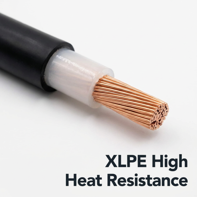
Code Mean:ZR-Flame Retardant,YJ-XLPE Insulation,V-PVC Outer Sheathed
ZR-YJV 1×120 mm² — Technical Dossier
1. Scope & Certification. This dossier covers the ZR-YJV 1×120, a single-core, flame-retarded power cable built to the CU/XLPE/PVC formula and rated 0.6/1 kV (Um = 1.2 kV), 50 Hz. Compliance basis: GB/T 12706.1 / IEC 60502-1 for construction and testing, GB/T 3956 / IEC 60228 for the conductor, and GB/T 19666 together with GB/T 18380 for fire performance. "ZR" marks the cable as flame-retardant; unless an A/B class is ordered, class ZC applies.
2. Bill of Materials (Layer Stack). The cross-section, moving outward, comprises:
| Layer | Material & make-up | Thickness | Diameter |
|---|---|---|---|
| Core | Plain annealed copper, Class 2, 24 × 2.52 mm (24/2.52) concentric stranding, nominal 120 mm² | — | ≈ 12.4 mm (compact) / 12.6 mm (round-lay) |
| Dielectric | Cross-linked polyethylene (XLPE) | 1.2 mm | ≈ 15.0 mm over insulation |
| Jacket | Flame-retarded PVC, ST2, black | 1.5 mm | ≈ 17.8 mm overall |
Unit weight ≈ 1290 kg/km (the copper core alone accounts for ≈ 1067 kg/km), with the overall diameter spanning 17.8–19.1 mm depending on the maker's stranding practice.
3. Electrical Design Values. DC conductor resistance is capped at 0.153 Ω/km at 20 °C; the routine high-voltage check is 3.5 kV AC for 5 minutes with no breakdown. On the dielectric side, XLPE volume resistivity holds at ≥ 1×10¹² Ω·cm and finished-cable insulation resistance is typically ≥ 36.7 MΩ·km at 20 °C; single-core capacitance stays ≤ 0.45 μF/km. Reference ampacity reaches ≈ 400 A in free air (30 °C, single core) and ≈ 380 A direct-buried, both subject to grouping, ambient and installation derating per GB/T 16895 / IEC 60364.
4. Thermal & Mechanical Data. The thermoset XLPE permits a continuous conductor temperature of 90 °C and a short-circuit ceiling of 250 °C for up to 5 s. Service ambient spans −20 to +45 °C, and laying must not start below 0 °C unless the drum is pre-warmed. For single-core runs, keep the bending radius no tighter than 20 × OD.
| ZR-YJV 1×120 mm² Flame-Retardant Copper-Conductor XLPE-Insulated PVC-Sheathed Power Cable — Product Parameters (0.6/1 kV) | |||||
| Construction: CU / XLPE / PVC • Standards: GB/T 12706.1, IEC 60502-1 (cable), GB/T 3956 (conductor), GB/T 19666 & GB/T 18380 (flame retardance) • Nominal values for reference — confirm against factory test certificate | |||||
| No. | Category | Parameter | Value | Unit | Notes / Standard Reference |
| A. Product Identification | |||||
| 1 | Identification | Product name | Flame-retardant copper-conductor XLPE-insulated PVC-sheathed power cable | — | Designation ZR-YJV; "ZR" = flame-retardant (halogen-containing) |
| 2 | Identification | Model designation | ZR-YJV 1×120 | — | Cu / XLPE / PVC |
| 3 | Identification | Design standards | GB/T 12706.1; IEC 60502-1 | — | Conductor: GB/T 3956 / IEC 60228; flame retardance: GB/T 19666, GB/T 18380; safety: CCC / production licence |
| 4 | Identification | Rated voltage U0/U | 0.6/1 | kV | Max system voltage Um = 1.2 kV |
| 5 | Identification | Rated frequency | 50 | Hz | AC power distribution |
| 6 | Identification | Number of cores | 1 | — | Single-core cable |
| 7 | Identification | Nominal cross-sectional area | 120 | mm² | Nominal conductor cross-section per GB/T 3956 |
| B. Cable Construction (from conductor to outer sheath) | |||||
| 8 | Conductor | Material | Plain annealed copper (Cu) | — | High-conductivity electrolytic / oxygen-free copper |
| 9 | Conductor | Conductor class | Class 1 or Class 2 (typical: Class 2, stranded) | — | GB/T 3956 / IEC 60228 |
| 10 | Conductor | Typical stranding construction | 24 wires × 2.52 mm (24/2.52); some manufacturers use 37 × 2.03 | — | Class 2 round stranded; nominal section ≈ 120 mm² |
| 11 | Conductor | Conductor diameter | ≈ 12.4 | mm | ≈ 12.4 mm compact (12.4–12.6 mm; 24/2.52 → ≈ 12.6 mm regular stranding) |
| 12 | Conductor | Max. DC resistance of conductor at 20 °C | 0.153 | Ω/km | GB/T 3956, Class 2 copper; acceptance criterion for 120 mm² |
| 13 | Insulation | Material | Cross-linked polyethylene (XLPE) | — | Thermally cross-linked; natural/transparent colour |
| 14 | Insulation | Nominal insulation thickness | 1.2 | mm | GB/T 12706.1 / IEC 60502-1 (0.6/1 kV, 120 mm²) |
| 15 | Insulation | Diameter over insulation | ≈ 15.0 | mm | ≈ 12.6 + 2 × 1.2 (calculated; 15.0 for regular stranding) |
| 16 | Sheath | Material | Flame-retardant polyvinyl chloride (PVC, ST2 type) | — | Colour: black (or as ordered) |
| 17 | Sheath | Nominal sheath thickness | 1.5 | mm | GB/T 12706.1 / IEC 60502-1 |
| 18 | Dimensions | Approx. overall diameter | 17.8 | mm | ≈ 17.8 mm (17.8–19.1 mm across sources: cabhr 17.8 mm; ahtk 19.1 mm) |
| 19 | Dimensions | Approx. cable weight | ≈ 1290 | kg/km | cabhr & ahtk agree at 1290 kg/km (copper alone ≈ 1067 kg/km) |
| C. Electrical Performance | |||||
| 20 | Electrical | Max. DC conductor resistance at 20 °C | 0.153 | Ω/km | GB/T 3956; routine measurement |
| 21 | Electrical | Power-frequency withstand voltage (routine test) | 3.5 kV / 5 min, no breakdown | — | AC 50 Hz; per GB/T 12706.1 / IEC 60502-1 |
| 22 | Electrical | Insulation resistance (finished cable, 20 °C) | ≥ 36.7 | MΩ·km | Typical finished-cable reference for 0.6/1 kV XLPE cables; varies with geometry and manufacturer test method |
| 23 | Electrical | XLPE volume resistivity at 20 °C | ≥ 1 × 10¹² | Ω·cm | Material-level requirement (manufacturer reference) |
| 24 | Electrical | Capacitance (single-core, approx.) | ≤ 0.45 | μF/km | Manufacturer reference value |
| 25 | Electrical | Reference ampacity — in air, 30 °C, single core | ≈ 400 | A | cabhr table (400 A); depends on laying, grouping, ambient — apply correction factors per GB/T 16895 / IEC 60364 |
| 26 | Electrical | Reference ampacity — direct burial, 25 °C | ≈ 380 | A | cabhr table; depends on soil thermal resistivity and depth |
| D. Thermal Performance | |||||
| 27 | Thermal | Max. continuous conductor temperature | 90 | °C | XLPE insulation temperature class |
| 28 | Thermal | Max. conductor temperature under short-circuit (≤ 5 s) | 250 | °C | Per GB/T 12706.1 / IEC 60502-1 |
| 29 | Thermal | Ambient service temperature range | -20 to +45 | °C | Per Qifan datasheet family; check project specification |
| 30 | Thermal | Min. installation (laying) temperature | 0 | °C | Pre-heat the cable if ambient is below 0 °C |
| E. Flame Retardance (ZR) | |||||
| 31 | Flame retardance | Flame-retardant class | ZC (class C) by default for "ZR" | — | GB/T 19666; ZA / ZB available on request; halogen-containing PVC (not LSZH) |
| 32 | Flame retardance | Single-cable vertical flame-spread test | Pass | — | GB/T 18380.12 |
| 33 | Flame retardance | Bunched flame-spread test (class C) | Char extent ≤ 2.5 m above burner bottom edge | — | GB/T 18380.35: non-metallic volume ≥ 1.5 L/m; flame application 20 min |
| 34 | Flame retardance | Halogen content | Halogen-containing (PVC) | — | For low-smoke, zero-halogen requirement select WDZ-YJY (LSZH) type |
| F. Installation | |||||
| 35 | Installation | Min. bending radius — single-core cable | 20 × OD | — | Qifan & Huaneng datasheets; OD = actual cable diameter |
| 36 | Installation | Laying methods | Conduit, tray, cable trench, tunnel, duct, supported/suspended aerial | — | Also direct burial with mechanical protection where permitted |
| 37 | Installation | Site withstand test after installation | DC 4U0 = 2.4 kV, 15 min (recommended) | — | Per utility procurement standard Q/GDW 13244.1-2018; practice may vary by project |
| G. Packing & Delivery | |||||
| 38 | Packing | Standard delivery length | 100 m per coil/drum (or as ordered) | — | Typical industry practice; custom lengths available |
| 39 | Packing | Cable marking | Model, rated voltage, manufacturer, year of manufacture, sequential length marks | — | Per GB/T 6995 / project specification |
| 40 | Packing | Packing form | Wooden drum / coil / export packing | — | As per customer requirement |
5. Fire-Retardancy Proof. The PVC jacket earns the ZC rating: it passes the single-cable vertical burn (GB/T 18380.12) and the category-C bunched burn (GB/T 18380.35 — ≥ 1.5 L/m non-metallic content, 20-minute flame, char extent ≤ 2.5 m). The PVC chemistry does release halogen in fire; switch to WDZ-YJY where low-smoke zero-halogen is a hard requirement.
6. Test & Verification Programme. Routine (every length): DC resistance ≤ 0.153 Ω/km; 3.5 kV/5 min withstand; dimensional audit (insulation ≥ 1.2 mm, sheath ≥ 1.5 mm). Sample: hot-set on the XLPE (200 ± 3 °C, 15 min, 0.2 MPa — elongation under load ≤ 175 %, permanent set ≤ 15 %); stranding and diameter checks. Type: flame tests and mandrel bending. Post-installation: site DC test at 4U0 = 2.4 kV / 15 min (Q/GDW 13244.1-2018 practice).
| ZR-YJV 1×120 mm² — Test / Verification Parameters (per GB/T 12706.1 & IEC 60502-1) | ||||
| Test Stage | Test Item | Method / Standard | Requirement / Acceptance Criterion | Notes |
| Routine test | Conductor DC resistance measurement | GB/T 3956 (IEC 60228) | ≤ 0.153 Ω/km at 20 °C | Measured on every production length |
| Routine test | Power-frequency withstand voltage | GB/T 12706.1 / IEC 60502-1 | 3.5 kV AC, 5 min, no breakdown | Applied between conductor and water/earth; 50 Hz |
| Routine test | Construction check — insulation & sheath thickness, outer diameter | GB/T 2951 | Within GB/T 12706.1 tolerances | Insulation ≥ 1.2 mm nominal; sheath ≥ 1.5 mm nominal |
| Sample test | Hot set (thermal elongation) test — XLPE insulation | GB/T 12706.1 §16.3.13 / GB/T 2951.11 | 200 ± 3 °C, 15 min, stress 0.2 MPa: elongation under load ≤ 175 %; permanent elongation after cooling ≤ 15 % | Verifies degree of cross-linking |
| Sample test | Conductor construction & diameter check | GB/T 3956 | Class 2; 24 × 2.52 mm; Ø ≈ 12.4 mm | Sampled per batch |
| Type test | Single-cable vertical flame-spread test (flame retardance) | GB/T 18380.12 | No flame spread; charring does not reach top reference point | ZR / ZC flame-retardant property |
| Type test | Bunched flame-spread test, class C | GB/T 18380.35 | Char extent ≤ 2.5 m above burner bottom edge; flame application 20 min; non-metallic volume ≥ 1.5 L/m | Class ZC per GB/T 19666 |
| Type test | Bending test (mechanical) | GB/T 12706.1 | Bend around specified mandrel without insulation/sheath damage | Mandrel diameter related to cable OD |
| Post-installation | DC withstand test after installation | Q/GDW 13244.1-2018 (recommended practice) | 4U0 = 2.4 kV DC, 15 min, no breakdown | For new installations; verify project specification |
| Optional | Insulation resistance measurement at 20 °C | Manufacturer test method | ≥ 36.7 MΩ·km (typical finished-cable value) | Not a routine item in GB/T 12706.1; confirm with factory |
| Optional | XLPE volume resistivity at 20 °C | Manufacturer / material test | ≥ 1 × 10¹² Ω·cm | Material-level reference |
7.Cross Section Structure
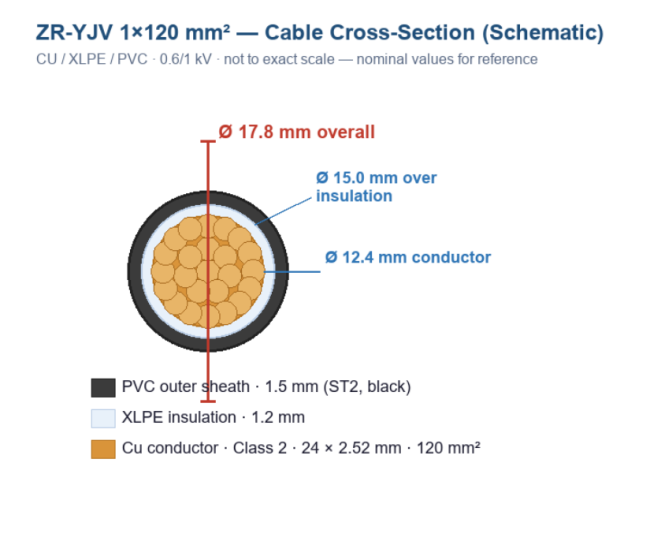
| ZR-YJV 1×120 mm² — Cable Cross-Section Structure (Schematic) | |||||
| Layers from conductor to outer sheath · nominal values per GB/T 12706.1 / IEC 60502-1 · not to exact scale | |||||
| No. | Layer | Material / Construction | Nominal Thickness (mm) | Diameter (mm) | Function / Remarks |
| 1 | Conductor (Cu) | Annealed copper, Class 2 stranded — 24 × 2.52 mm (24/2.52), nominal 120 mm² | — | ≈ 12.4 (Ø) | Current-carrying element; max DC resistance ≤ 0.153 Ω/km @ 20 °C |
| 2 | Insulation (XLPE) | Cross-linked polyethylene | 1.2 | ≈ 15.0 (Ø over insulation) | Dielectric barrier; rated 90 °C continuous; withstands 3.5 kV / 5 min |
| 3 | Outer sheath (PVC) | Flame-retardant PVC, ST2 type, black | 1.5 | ≈ 17.8 (Ø overall) | Mechanical & moisture protection; flame retardance ZC (ZR) per GB/T 19666 |
| Key Dimensions & Properties | |||||
| Overall diameter | 17.8 | mm | 17.8–19.1 mm across sources (cabhr 17.8; ahtk 19.1) | ||
| Approx. cable weight | ≈ 1290 | kg/km | cabhr & ahtk agree; Cu core alone ≈ 1067 kg/km | ||
| Rated voltage | 0.6/1 | kV | AC 50 Hz; max system voltage Um = 1.2 kV | ||
| Max conductor temperature | 90 / 250 | °C | Continuous / short-circuit (≤ 5 s) | ||
| Min. bending radius (single-core) | 20 × OD | — | OD = actual cable diameter | ||
| Flame-retardant class | ZC (ZR) | — | GB/T 19666 | ||
| Product Structure Introduction — ZR-YJV 1×120 mm² | |||
| Layered construction description, from conductor to outer sheath · per GB/T 12706.1 & IEC 60502-1 · CU / XLPE / PVC · 0.6/1 kV | |||
| 1. Cable Architecture at a Glance | |||
| This is a one-conductor, fire-retardant feeder cable for 0.6/1 kV AC systems (Um = 1.2 kV, 50 Hz). The physical layout is strictly concentric: a round stranded copper core sits at the centre, wrapped by a cross-linked polyethylene dielectric, and finished with a halogen-bearing flame-retardant PVC jacket. Design and tests follow GB/T 12706.1 / IEC 60502-1; conductor sizing follows GB/T 3956 / IEC 60228; fire behaviour is governed by GB/T 19666. | |||
| Representative envelope: 17.8 mm overall diameter (17.8–19.1 mm per source) and ≈ 1290 kg/km unit weight. The cable is shipped on 100 m drums or coils and suits fixed industrial and utility runs. | |||
| 2. The Copper Core | |||
| Plain annealed copper, normally drawn as Class 2, is stranded into twenty-four 2.52 mm wires (24/2.52) — a classic concentric construction — to realise the nominal 120 mm² section. The multi-wire bundle provides the flexibility required for site handling while capping DC resistance at 0.153 Ω/km at 20 °C. Core diameter lands near 12.4 mm for compact stranding, rising to about 12.6 mm when fully round-lay. | |||
| 3. The XLPE Dielectric | |||
| Over the core, a 1.2 mm layer of cross-linked polyethylene is extruded, bringing the diameter over insulation to ≈ 15.0 mm. Chemical cross-linking converts the thermoplastic into a thermoset network, which lifts the continuous operating limit to 90 °C and the short-circuit limit to 250 °C (max 5 s). This layer provides the primary electrical barrier — volume resistivity ≥ 1×10¹² Ω·cm at 20 °C and a pass at 3.5 kV AC for 5 minutes on the finished length. | |||
| 4. The PVC Jacket | |||
| The outermost 1.5 mm shell is a black, flame-retarded PVC compound (ST2). It absorbs mechanical abuse, resists moisture ingress and delivers the “ZR” fire rating — class ZC per GB/T 19666, demonstrated through the single vertical burn (GB/T 18380.12) and the category-C bunched burn (GB/T 18380.35, char limit 2.5 m). Because the jacket is PVC, the cable releases halogen under fire; projects that demand low smoke and zero halogen should call for WDZ-YJY instead. | |||
| 5. Deployment Guidance | |||
| • Suitable for main feeders, motor circuits and panel supplies at the 120 mm² copper level; standard drum 100 m. • Keep the bend radius above 20 × OD when laying a single core. • Do not install at temperatures below 0 °C without pre-warming; normal service range is −20 to +45 °C. • Always reconcile nominal values with the factory certificate and the GB/T 12706.1 / IEC 60502-1 test report. |
8. Site Handling & Precautions. Keep drums upright and unroll without dragging the jacket over sharp edges; allow slack at terminations instead of over-tensioning. Protect the sheath from UV if laid outdoors long-term. Re-check insulation integrity before energising and never exceed the 3.5 kV/5 min test level during site verification unless the project spec says otherwise.
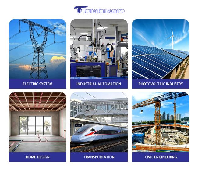
9. Fields of Use. Main and sub-main feeders, motor and pump circuits, transformer secondary tails, switchboard interconnections and industrial risers at 0.6/1 kV — in trays, conduits, trenches, tunnels and ducts, indoors and in protected outdoor locations.
10. Procurement Notes. Order as: ZR-YJV 0.6/1 kV 1×120, stating length, drum type, marking and any special sheath colour. Delivery is normally 100 m per drum/coil. Always reconcile the figures in this dossier with the factory quality certificate and the GB/T 12706.1 / IEC 60502-1 test report before installation.
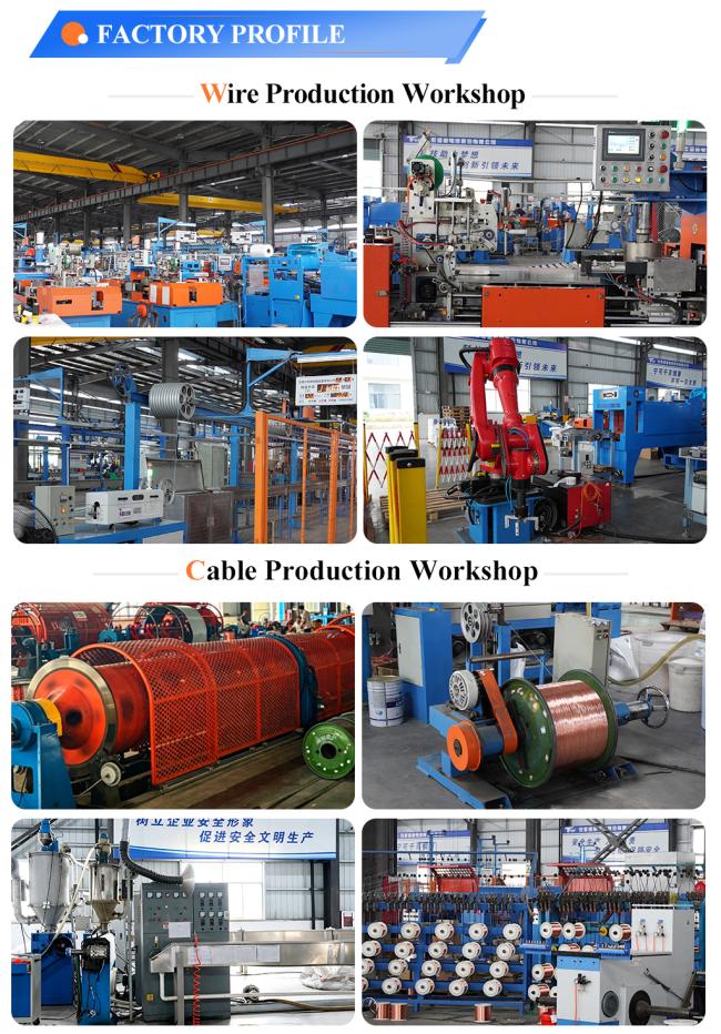
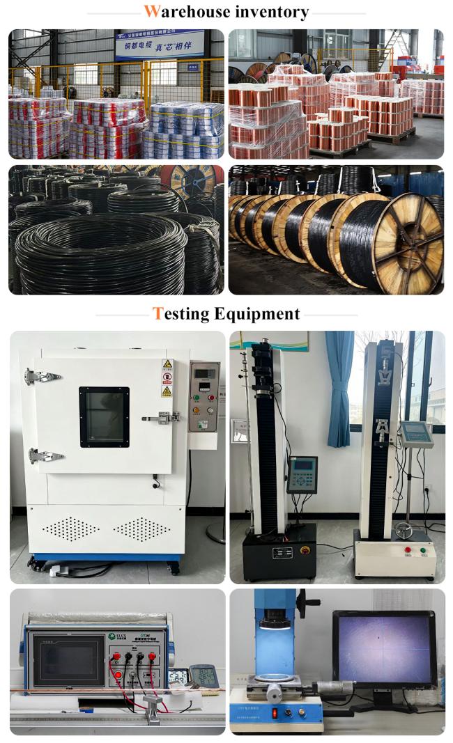
11. Fctory overview

Get in Touch
Have questions about our products or want to discuss a custom order? Our team is ready to help you.