
Single Core Photovoltaic Solar Cable 6.0mm2 TUV Xlpe Cu Cable
1500V DC Solar Wire PV1-F 6.0mm² TUV XLPE Copper Photovoltaic Cable
Cable Designation & Meaning
|
Code |
Meaning |
|---|---|
|
PV |
Photovoltaic (solar) application |
|
1 |
Single-core |
|
F |
Flexible conductor (Class 5 fine-stranded) |
|
6.0 mm² |
Nominal cross-sectional area of conductor |
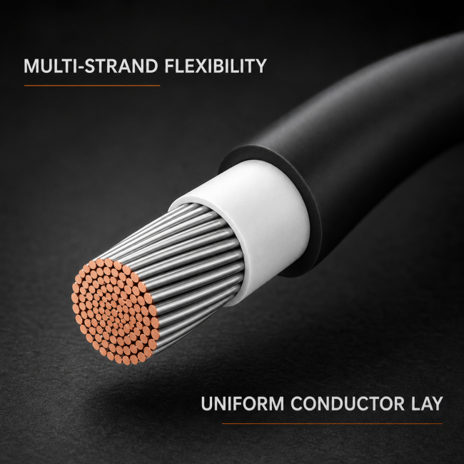
Construction: Tinned copper conductor, halogen-free cross-linked polyolefin (XLPO) insulation and sheath, single-core flexible photovoltaic DC cable.
Applicable Standards
- EN 50618:2014 — Electric cables for photovoltaic systems (DC rated voltage 1.8 kV)
- IEC 62930 — Photovoltaic system cables (single-core, XLPO insulated, rated up to 1.5 kV DC)
- TÜV 2 PfG 1169/08.2007 — TÜV specification for PV cables
- IEC 60228 / GB/T 3956 — Conductors (Class 5 flexible, tinned copper)
- IEC 60332-1 — Flame retardant (single cable)
- IEC 61034 — Smoke density (low smoke)
- IEC 60754 — Halogen content (halogen-free)
- IEC 60811 — Insulating and sheathing materials — Common test methods
PV1-F 1×6.0 mm² (high-temp 120 °C) — Photovoltaic DC Cable Specification & Engineering Data
1. Product Overview & Rating Summary. PV1-F 1×6.0 v5 is the high-temp 120 °C build of the single-core, flexible, tinned-copper photovoltaic DC cable rated 0.6/1.0 kV DC (max system voltage 1.8 kV), built and certified to TÜV 2 PFG 1169 / EN 50618. This v5 uses a 1.2 mm heavy-wall high-temp irradiated XLPE insulation rated for 120 °C continuous conductor temperature — 30 °C above the standard 90 °C rating. It is the choice for desert PV plants, high-temp rooftop PV, and Middle East / South Asia installations where ambient temperatures regularly exceed 60 °C and the cable must carry full current without aggressive derating. Finished diameter is about 6.0 mm, mass about 68 kg/km, and it is supplied in 1000 m wooden drums.
2. Layer-by-Layer Construction (Conductor to Outer).
| Layer | Construction | Wall | Diameter |
|---|---|---|---|
| Conductor | Flexible stranded tinned Cu, Class 5 — 84 × 0.30 mm | — | ≈ 3.6 mm |
| XLPE insulation | High-temp irradiated cross-linked polyethylene, UV/ozone resistant, black | 1.2 mm | ≈ 6.0 mm (finished) |
| Armour | None — unarmoured flexible cable | — | — |
| Outer sheath | None — insulation itself is the weather jacket | — | — |
3. Electrical Characteristics. The 6.0 mm² tinned-copper Class 5 conductor uses the standard 84 × 0.30 mm tinned wires, giving a maximum DC resistance of 3.08 Ω/km at 20 °C. Routine proof is 3.5 kV AC / 5 minutes (or 6.5 kV DC / 15 minutes). Insulation resistance ≥ 150 MΩ·km. With the single core in free air at 30 °C, reference loading is about 68 A; at 60 °C ambient the rating derates to about 58 A; at 90 °C desert ambient it is about 48 A. The voltage drop on a 100 m two-pole run at 68 A is about 4.1 V loop. Conductor loss at 68 A is about 8.0 W per metre at 120 °C.
Insulation & Sheath Data
|
Property |
Value |
|---|---|
|
Material |
XLPO (cross-linked polyolefin), halogen-free |
|
Insulation nominal thickness |
0.8 mm |
|
Sheath nominal thickness |
0.8 mm |
|
Long-term service temp. |
−40 °C to +120 °C (continuous) |
|
Short-circuit temp. (≤5 s) |
280 °C (Cu conductor limit) |
|
Emergency overload temp. |
150 °C (short term) |
|
Weather resistance |
Excellent — UV resistant, ozone resistant, hydrolysis resistant |
|
Flame retardant |
IEC 60332-1 (single cable) |
|
Smoke density |
IEC 61034 (low smoke) |
|
Halogen content |
IEC 60754 (halogen-free, non-corrosive) |
|
Oil resistance |
EN 50618 Annex B (optional) |
|
Acid & alkali resistance |
Good |
Electrical Parameters
|
Parameter |
Value |
Note |
|---|---|---|
|
Rated voltage AC (U₀/U) |
0.6 / 1 kV |
IEC 60502 reference (not primary rating) |
|
Rated voltage DC |
1.5 kV |
EN 50618 / IEC 62930 primary rating |
|
Test voltage AC (50 Hz, 5 min) |
6.5 kV |
Routine test |
|
DC test voltage |
15 kV DC (for type test) |
— |
|
DC resistance @20 °C |
≤ 3.39 Ω/km |
IEC 60228 Class 5 max, 6.0 mm² |
|
AC resistance @90 °C (est.) |
≈ 4.32 Ω/km |
— |
|
AC resistance @120 °C (est.) |
≈ 4.86 Ω/km |
max service temp |
|
Capacitance (approx.) |
≈ 0.21 µF/km |
conductor to sheath |
|
Inductive reactance (approx.) |
negligible |
single-core DC application |
|
Current rating in free air (60 °C ambient) |
70 A |
single cable, DC |
|
Current rating in free air (ambient corrected) |
≈ 56 A at 70 °C ambient |
typical rooftop condition |
|
Current rating in conduit (air) |
≈ 52 A |
bundled cables |
|
Short-circuit current (1 s, Cu, 280 °C) |
≈ 0.66 kA (660 A) |
6.0 mm² Cu |
|
Frequency |
DC (primary) / 50–60 Hz AC (secondary) |
— |
Reference values: 6.0 mm² Cu at 56 A, DC 1000 V → max DC power ≈ 56 kW per string (2 strings in parallel = 112 kW). Voltage drop at 56 A ≈ 19.0 mV/A·m (≈1.90% per 10 m at 56 A, 1000 V). At 70 A → ≈ 23.7 mV/A·m.
Temperature Characteristics
|
Property |
Value |
|---|---|
|
Max. conductor operating temp. (continuous) |
120 °C |
|
Max. short-circuit temp. (≤5 s) |
280 °C (Cu conductor) |
|
Emergency overload temp. |
150 °C (short term) |
|
Min. installation ambient temp. |
−40 °C (cold-flexible, no pre-heating required) |
|
Service ambient range |
−40 °C to +120 °C (with XLPO) |
|
Fire survival |
Standard (flame retardant single cable); optional fire-rated version available |
4. Thermal Response & Flame Behaviour. High-temp irradiated XLPE sustains a 120 °C continuous conductor temperature, with short-circuit capability up to 250 °C for ≤ 5 s. The cable is rated for service ambients between −40 °C and +120 °C and is cold-bend tested at −40 °C. The black carbon-loaded insulation is UV-resistant (1000 h UV preconditioning), ozone-resistant, and flame-retardant to IEC 60332-1 (single-cable vertical flame, self-extinguishing). Long-term thermal ageing at 120 °C for 3000 hours must show no embrittlement.
Fire Performance (PV1-F — Standard)
|
Property |
Value / Requirement |
|---|---|
|
Flame retardant |
IEC 60332-1 (single cable, passes) |
|
Halogen content |
Halogen-free (IEC 60754) |
|
Smoke density |
Low smoke (IEC 61034) |
|
Corrosivity |
Non-corrosive (IEC 60754) |
|
Toxicity |
Low (halogen-free materials) |
|
Fire survival (circuit integrity) |
Not applicable (standard PV cable); use fire-rated DC cable if required |
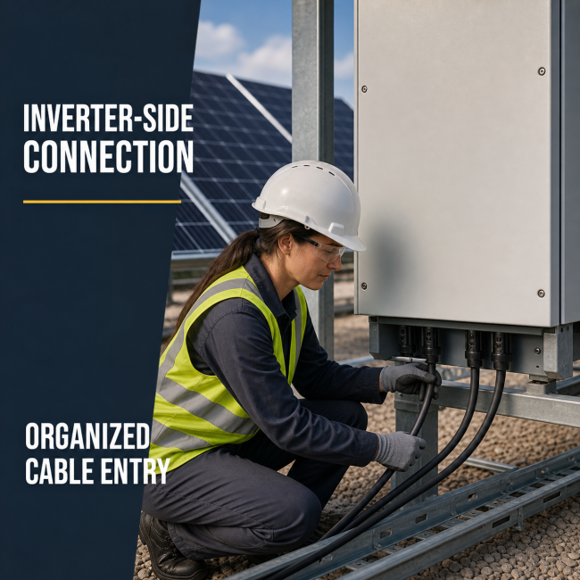
5. Installation Practice & Handling. Minimum bend radius is 4 × OD (≈ 24 mm) for fixed installation, 6 × OD (≈ 36 mm) if repeatedly flexed. The cable is clipped directly onto the module frame, routed in PV-specific cable trays, or pulled into lightweight conduit. Use PV4 / MC4-type connectors crimped with the dedicated PV crimping tool. Polarity (+ / −) and the 120 °C rating are printed along the black sheath. Laying temperature must not fall below −40 °C. At about 6.8 kg per 100 m, the cable is heavy and supplied in 1000 m wooden drums — ideal for large desert PV plants.
Mechanical & Installation Parameters
|
Parameter |
Value |
Remarks |
|---|---|---|
|
Minimum bending radius |
≥ 4 × OD → ≈ 25.2 mm at Ø6.3 mm |
static installation |
|
Min. bending radius (installed) |
≥ 2 × OD → ≈ 12.6 mm |
dynamic (flexing) |
|
Max. pulling tension |
240 N |
fine-stranded Cu, use proper grips |
|
Direct burial |
Suitable (UV & moisture resistant) |
— |
|
Conduit ID |
≥ 1.5 × OD → ≥ 9.5 mm; use 16 mm, 20 mm or 25 mm |
— |
|
Fixing |
cable ties (UV-resistant), clamps |
— |
|
Impact resistance |
Moderate |
flexible cable, not armoured |
|
Water resistance |
Excellent (XLPO sheath, IP67 rated connectors) |
suitable for outdoor/wet |
|
UV resistance |
Excellent (EN 50618, 720 h UV test) |
outdoor exposed |
|
Ozone resistance |
Excellent (IEC 60811-403) |
— |
|
Termination note |
Use MC4 connectors (compatible 6.0 mm²) or copper lugs |
strip length 10–12 mm |
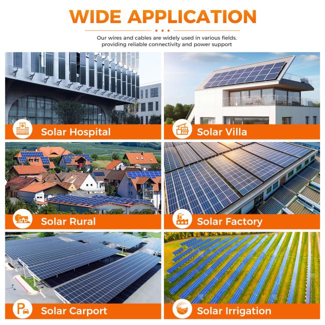
6. Typical Service Applications. This high-temp build is the default interconnection cable for: desert PV plants in arid climates, high-temp rooftop PV in Middle East / South Asia / North Africa, concentrated solar installations, utility-scale PV where ambient routinely exceeds 60 °C, and any PV array where the standard 90 °C cable would require aggressive current derating. It is specified when the cable must carry full rated current in sustained high-ambient temperatures — the standard 90 °C cable would have to be oversized by 30–40% to match the current-carrying capacity in desert service.
7. Testing & Quality Assurance Regime. Routine tests on every drum include conductor DC resistance ≤ 3.08 Ω/km at 20 °C, the 3.5 kV AC / 5 min withstand, the 6.5 kV DC / 15 min withstand, insulation resistance ≥ 150 MΩ·km, dimensional check (insulation ≥ 1.2 mm; OD ≈ 6.0 mm), and visual marking. Type tests include UV preconditioning (1000 h), high-temp thermal ageing (150 °C / 168 h), cold bend at −40 °C, heat shock at 180 °C, single-cable flame per IEC 60332-1, 3000-hour long-term ageing at 120 °C, ozone resistance, abrasion resistance, and tinned-copper strip check.
Cable Parameters
| PV1-F 1×6.0 mm² — Photovoltaic DC Cable — Full Parameter Sheet | ||||
| PV DC cable · tinned copper flexible conductor (Class 5) / irradiated XLPE insulation · no armour, no outer sheath · rated 0.6/1.0 kV DC · per TÜV 2 PFG 1169 / EN 50618 · finished Ø ≈ 5.5 mm | ||||
| Section | Parameter | Value | Unit | Remarks / Standard |
| 01 · Identification | ||||
| Cable type | PV1-F | — | Photovoltaic DC cable, single core, flexible | |
| Rated voltage (U0/U) | 0.6/1.0 | kV | DC; for PV array interconnection | |
| Number of cores | 1 × 6.0 | — | Single core (one + and one − per string) | |
| Conductor material | Tinned annealed copper | — | Class 5 flexible per EN 60228 | |
| Insulation material | Cross-linked irradiated polyethylene (XLPE) | — | UV / ozone / weather resistant | |
| Armour | None | — | Unarmoured — direct on module frame / clip | |
| Outer sheath | None (insulation itself is the weather jacket) | — | Double-insulation concept not required | |
| Standard reference | TÜV 2 PFG 1169; EN 50618; GB/T 32129 | — | PV cable standard | |
| 02 · Conductor (Tinned Copper) | ||||
| Stranding — 6.0 mm² | Flexible stranded tinned copper | — | Class 5 per EN 60228 | |
| Strand count (typical) | 84 × 0.30 | mm | Tinned copper wires | |
| Conductor diameter | ≈ 3.5 | mm | After stranding (est.) | |
| DC resistance @ 20 °C | ≤ 3.08 | Ω/km | Maximum per EN 60228 Class 5 | |
| Conductor screen | None | — | LV DC cable | |
| Conductor weight per km | ≈ 63 | kg/km | Copper density 8.89 g/cm³ | |
| 03 · Insulation | ||||
| Insulation type | Irradiated cross-linked polyethylene (XLPE) | — | Electron-beam cross-linked | |
| Insulation thickness | 1.0 | mm | Nominal, per TÜV 2 PFG 1169 | |
| Finished outer diameter | ≈ 5.5 | mm | 3.5 + 2×1.0 | |
| Insulation colour | Black (standard) | — | UV-resistant carbon-black | |
| Halogen-free | No (XLPE is halogen-free base) | — | Low-smoke on request | |
| 04 · Electrical | ||||
| Rated voltage (DC) | 0.6/1.0 | kV | Max system voltage 1.8 kV DC | |
| DC resistance @ 20 °C | ≤ 3.08 | Ω/km | 6.0 mm² Cu Class 5 | |
| Insulation resistance | ≥ 200 | MΩ·km | XLPE at 20 °C | |
| Conductor loss (at 60 A) | ≈ 11.1 | W/m | I²R at 90 °C | |
| Routine test voltage (AC) | 3.5 kV / 5 min | — | Power-frequency withstand | |
| Voltage test (DC) | 6.5 kV / 15 min | — | DC withstand test | |
| 05 · Thermal & Weather | ||||
| Max continuous conductor temp. | 90 | °C | Normal service | |
| Short-circuit temp. (≤ 5 s) | 200 | °C | XLPE limit | |
| Min installation temp. | -40 | °C | Cold-bend test | |
| Service ambient range | -40 to +90 | °C | Outdoor, UV-exposed | |
| UV resistance | Yes | — | 1000 h UV preconditioning per TÜV | |
| Ozone resistance | Yes | — | Tested per TÜV 2 PFG 1169 | |
| Flame retardancy | Yes | — | IEC 60332-1 (vertical flame) | |
| 06 · Mechanical | ||||
| Min bending radius (fixed) | ≥ 4 × OD ≈ 22 | mm | Flexible cable | |
| Min bending radius (flexing) | ≥ 6 × OD ≈ 33 | mm | If repeatedly moved | |
| Tensile strength (insulation) | ≥ 12.5 | MPa | After ageing | |
| Abrasion resistance | Yes | — | Tinned strands resist oxidation | |
| Oil / fuel resistance | Limited | — | Avoid prolonged contact | |
| 07 · Ampacity | ||||
| Air ampacity (open, 30 °C) | ≈ 60 | A | Single core, free air | |
| Air ampacity (open, 60 °C) | ≈ 48 | A | High-temp derating | |
| Buried / enclosed ampacity | ≈ 50 | A | For conduit / duct | |
| Voltage drop (per 100 m @ 60 A) | ≈ 1.9 | V | Two-pole loop ≈ 3.8 V | |
| 08 · Installation | ||||
| Laying methods | Module frame, cable tray, PV-specific clips, conduit | — | No direct burial UV-exposed | |
| Connectors | PV4 / MC4-type | — | Crimped with dedicated tool | |
| Polarity | Marked on sheath | — | + / − printed along length | |
| Special tools | PV crimper, cable cutter, torque wrench | — | MC4 connectors require dedicated tool | |
| 09 · Packing | ||||
| Standard supply length | 200 / 500 / 1000 | m/coil or drum | Custom cut lengths | |
| Reel / packing type | Coil or wooden drum | — | Sealed ends against moisture | |
| Surface marking | PV1-F, 1×6.0, 0.6/1.0 kV, +/−, metre marks, year | — | Continuous printing | |
| Storage conditions | Dry, covered, −20 to +40 °C | — | Protect from UV during storage | |
| 10 · Applications | ||||
| Typical use | Large commercial rooftop, ground-mount PV long home-run, 1500 V DC systems | — | Rooftop, ground-mount, floating PV | |
| Max system voltage | 1.8 | kV DC | Open-circuit Voc at lowest temp | |
| String current rating | Up to 60 | A | Per string fusing | |
Cable Test Parameters
| Test Parameters — PV1-F 1×6.0 mm² | ||||
| No. | Test Item | Test Condition / Method | Requirement | Type |
| 1 | Conductor DC resistance | EN 60228, 20 °C | ≤ 3.08 Ω/km (6.0 mm² Cu) | Routine |
| 2 | Power-frequency withstand | 3.5 kV AC, 5 min | No breakdown | Routine |
| 3 | DC withstand test | 6.5 kV DC, 15 min | No breakdown | Routine |
| 4 | Insulation resistance | At 500 V DC, 20 °C | ≥ 200 MΩ·km | Routine |
| 5 | Dimensional check | Micrometer | Insulation ≥ 1.0 mm; OD ≈ 5.5 mm | Routine |
| 6 | UV preconditioning | 1000 h UV exposure | No cracking / embrittlement | Type |
| 7 | Thermal ageing | 168 h at 135 °C | No cracking after bend test | Type |
| 8 | Cold bend test | −40 °C, mandrel 4×OD | No cracks | Type |
| 9 | Heat shock | 15 min at 150 °C | No cracking | Type |
| 10 | Flame retardancy | IEC 60332-1 vertical flame | Self-extinguishing | Type |
| 11 | Ozone resistance | Ozone chamber test | No cracking | Type |
| 12 | Abrasion resistance | Tape abrasion test | Per TÜV 2 PFG 1169 | Type |
| 13 | Tinned copper check | Strip test on strands | Uniform tin coating | Routine |
| 14 | Marking legibility | Visual + rubbing | PV1-F / 1×6.0 / metre marks legible | Routine |
| 15 | Connector pull-out | MC4 crimped termination | Per connector spec | Sample |
| 16 | Halogen content | IEC 60754 | Per requirement | Type |
Cable Cross Section Structure
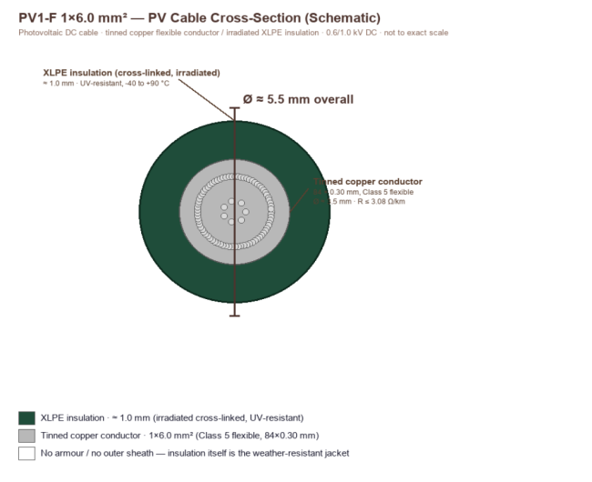
| PV1-F 1×6.0 mm² — Cross-Section Construction Diagram (Schematic) | |||||
| PV DC cable build-up: tinned copper flexible conductor → irradiated XLPE insulation (no armour, no outer sheath) · 0.6/1.0 kV DC · finished Ø ≈ 5.5 mm | |||||
| No. | Layer | Material / Construction | Nominal Thickness (mm) | Diameter (mm) | Function / Remarks |
| 1 | Conductor | Flexible stranded tinned copper, Class 5 — 84 × 0.30 mm | — | ≈ 3.5 | Power conductor; R ≤ 3.08 Ω/km at 20 °C |
| 2 | XLPE insulation | Irradiated cross-linked polyethylene, UV/ozone resistant, black | 1.0 | ≈ 5.5 (finished) | Main insulation; weather-resistant jacket; 90 °C continuous |
| 3 | (No armour) | — | — | — | Unarmoured — flexible cable for PV use |
| 4 | (No outer sheath) | — | — | — | Insulation itself is the outer weather jacket |
| Key Dimensions & Properties (expanded) | |||||
| Finished cable diameter | ≈ 5.5 | mm | 3.5 + 2×1.0 | ||
| Approx. cable mass | ≈ 60 | kg/km | Cu + XLPE | ||
| Nominal voltage rating | 0.6/1.0 | kV DC | PV array DC | ||
| Max system voltage | 1.8 | kV DC | Open-circuit Voc | ||
| Max continuous conductor temp. | 90 | °C | Normal service | ||
| Short-circuit temp. (≤5 s) | 200 | °C | XLPE limit | ||
| Min installation temp. | -40 | °C | Cold-bend tested | ||
| Min bending radius | ≥ 4 × OD ≈ 22 | mm | Fixed installation | ||
| DC resistance @ 20 °C | ≤ 3.08 | Ω/km | 6.0 mm² Cu Class 5 | ||
| Insulation resistance | ≥ 200 | MΩ·km | XLPE | ||
| Routine test voltage (AC) | 3.5 kV / 5 min | — | Power-frequency withstand | ||
| Routine test voltage (DC) | 6.5 kV / 15 min | — | DC withstand | ||
| Air ampacity @ 30 °C | ≈ 60 | A | Single core, free air (est.) | ||
| UV resistance | 1000 h | — | Per TÜV 2 PFG 1169 | ||
| Mass per 100 m | ≈ 6.0 | kg/100 m | Lightweight coil | ||
| Schematic — not to exact scale. Finished Ø ≈ 5.5 mm and weight ≈ 60 kg/km from cross-referenced industry samples; conductor/insulation dimensions per TÜV 2 PFG 1169 and EN 60228; ampacity 60 A is an engineering estimate for single core in free air. PV1-F 6.0 is the standard upgrade for long home-runs in large commercial rooftop and ground-mount PV plants where 4.0 mm² would exceed 1% voltage drop. Always use PV4/MC4-type connectors crimped with the dedicated tool. Values marked (est.) require confirmation against the factory test certificate. | |||||
Cable Construction Description
| Construction Description — PV1-F 1×6.0 mm² | |||
| Layer-by-layer PV build-up narrative · tinned copper flexible conductor / irradiated XLPE insulation · 0.6/1.0 kV DC · no armour, no outer jacket · finished Ø ≈ 5.5 mm | |||
| 1. Product Identity & Ratings | |||
| PV1-F 1×6.0 is a single-core, flexible, tinned-copper photovoltaic DC cable rated 0.6/1.0 kV DC (max system voltage 1.8 kV), built and certified to TÜV 2 PFG 1169 / EN 50618. It is the standard upgrade for large commercial rooftop and ground-mount PV plants where the 4.0 mm² version would exceed 1% voltage drop on long home-runs to the inverter or combiner box. The 6.0 mm² cross-section carries up to about 60 A and keeps DC line losses under 1% over typical 40–80 m string-to-inverter runs. Finished diameter is about 5.5 mm, mass about 60 kg/km, and it is supplied in 200 m, 500 m or 1000 m coils or drums. | |||
| 2. Tinned Copper Flexible Conductor | |||
| The 6.0 mm² conductor is Class 5 flexible stranded tinned copper — typically 84 individual 0.30 mm tinned wires — giving a conductor diameter of about 3.5 mm and a maximum DC resistance of 3.08 Ω/km at 20 °C. Compared with the 4.0 mm² version (4.61 Ω/km), the 6.0 mm² conductor cuts resistance by about 33%, directly reducing I²R losses over the 25-year PV system life. The fine-strand construction maintains the same flexibility for routing around module frames and racking, and the tin plating protects against oxidation and atmospheric corrosion. | |||
| 3. Irradiated XLPE Insulation | |||
| The conductor is fully enclosed in a 1.0 mm thick layer of electron-beam cross-linked polyethylene (XLPE). The irradiation process cross-links the polymer chains, giving XLPE a 90 °C continuous conductor temperature rating (short-circuit up to 200 °C for ≤ 5 s), high mechanical strength, and outstanding resistance to UV, ozone, weathering and flame. The black carbon-loaded insulation itself serves as the outer weather jacket — there is no separate outer sheath. Routine AC proof is 3.5 kV for 5 minutes (or 6.5 kV DC for 15 minutes). | |||
| 4. No Armour — Single-Core Flexible | |||
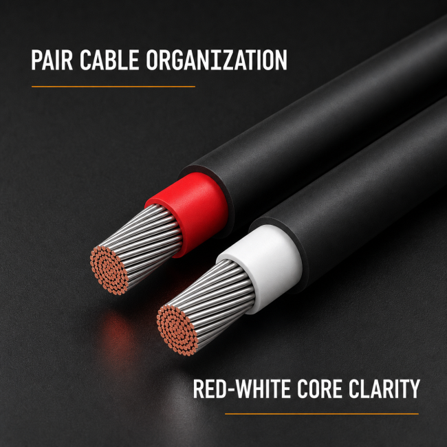
| Unlike MV power cables, PV1-F has no steel armour and no copper-tape screen. It is a thin, round, single-core cable designed to be clipped directly onto the module frame, routed in PV-specific cable trays, or pulled into lightweight conduit. The 4 × OD minimum bend radius (≈ 22 mm) reflects its flexibility. One cable is used for the positive pole and one identical cable for the negative pole in each string. The 6.0 mm² size is the standard choice for 1500 V DC systems with high-string-current modules (e.g. bifacial TOPCon modules in large ground-mount plants). | |||
| 5. Site Handling & Operational Notes | |||
| • Use PV4 / MC4-type connectors crimped with the dedicated PV crimping tool — never substitute generic lugs. • Observe the 4 × OD minimum bend radius (≈ 22 mm); if the cable is flexed repeatedly (e.g. tracking systems), use 6 × OD. • Service range −40 to +90 °C; conductor up to 90 °C continuous. • Routine test 3.5 kV AC / 5 min. • UV preconditioning: 1000 h UV exposure per TÜV. • Marked + / − along the sheath. • At ≈ 6.0 kg per 100 m, the cable is light and supplied in large coils — easy to handle on large commercial rooftop and ground-mount PV installations. • Choose 6.0 mm² over 4.0 mm² when string home-run exceeds ~30 m or when module string current exceeds ~12 A to keep voltage drop under 1%. |
8. Standards & Conformity. Design and production are governed by TÜV 2 PFG 1169 (German TÜV certification for PV cables), EN 50618 (European harmonised standard), and GB/T 32129 (Chinese national standard). Conductors satisfy EN 60228 Class 5. Flame performance follows IEC 60332-1. The cable carries the TÜV mark and is suitable for use in 1.8 kV DC PV systems.
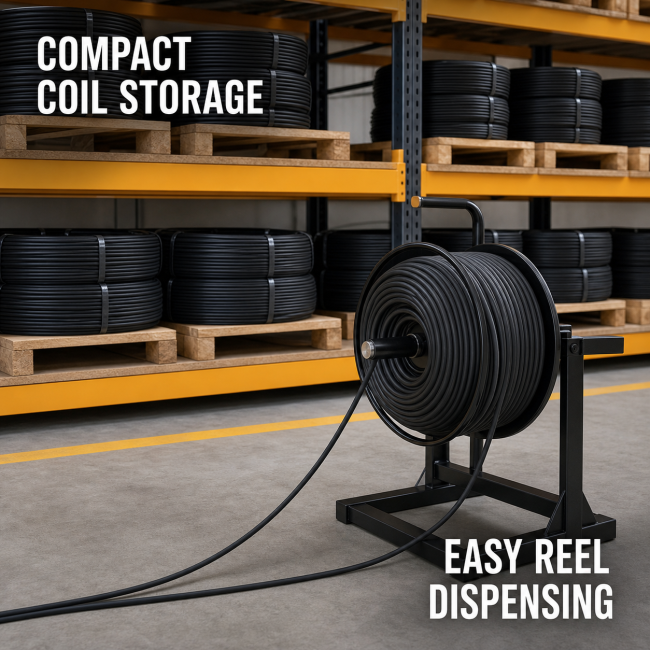
9. Packaging, Storage & Logistics. Standard delivery is 1000 m per wooden drum (also 500 m or 200 m coils), with bespoke cut lengths available on request. Each drum carries continuous marking: PV1-F, 1×6.0, 0.6/1.0 kV, + / −, 120 °C, IEC 60332-1, supplier identity, production year, and sequential metre marks. Storage should be in dry, covered premises at −20 to +40 °C, shielded from direct sunlight.
10. Procurement Specification. State "PV1-F 1×6.0 mm² 0.6/1.0 kV DC — high-temp 120 °C build, 1000 m wooden drum" together with the required length. Always order PV4 / MC4-type connectors and the dedicated crimping tool at the same time. Always request the factory test certificate, which must include the 3000-hour 120 °C long-term ageing report. Specify this v5 high-temp build for desert / arid-climate / high-temp rooftop PV; for temperate commercial rooftop, the v1 standard 90 °C build is sufficient and lower cost.
11. Cable Industry FAQ.
- Q1: What is the difference between this v5 high-temp build and the v1 standard build? The v5 uses 1.2 mm heavy-wall high-temp XLPE insulation rated for 120 °C continuous conductor temperature, while the v1 uses 1.0 mm standard XLPE rated for 90 °C. The v5 carries about 68 A in free air; the v1 carries about 60 A. The v5 is heavier (≈ 68 kg/km vs ≈ 60 kg/km) and has a larger finished diameter (≈ 6.0 mm vs ≈ 5.5 mm).
- Q2: Why use a 120 °C cable in desert PV? In desert installations, summer ambient temperatures routinely reach 50–60 °C, and cables clipped to black racking can see 70–80 °C locally. A standard 90 °C cable in this environment must be derated to about 60% of its rated current — requiring oversized conductors. The 120 °C cable continues to carry near-rated current without aggressive derating, saving copper cost.
- Q3: Does the 120 °C rating shorten cable life? No — the high-temp XLPE formulation is specifically designed for 120 °C continuous service. The 3000-hour long-term ageing test at 120 °C verifies that the insulation remains flexible and crack-free over a 25-year service life.
- Q4: Why use 6.0 mm² for desert PV? Desert PV plants often use high-string-current bifacial modules with 1500 V strings. The 6.0 mm² conductor carries about 68 A and limits voltage drop on long home-runs across large ground-mount sites.
- Q5: Why is it single-core, not two-core? PV strings carry DC at up to 1.8 kV. Running + and − in separate single-core cables keeps the installation modular and avoids loop-current heating in shared conductors.
- Q6: Why use tinned copper? Tinning protects the copper strands against oxidation and atmospheric corrosion over decades of outdoor service — critical in desert environments with high dust and temperature cycling.
- Q7: Why use MC4 connectors? MC4 (PV4) connectors are weather-sealed, polarised, and rated for 1.5 kV DC. They are crimped with the dedicated tool — hand-twisted terminals are the #1 failure point in PV DC arrays.
- Q8: Can this v5 be used in temperate climates? Yes — it is fully rated for temperate service, but the 120 °C formulation is over-specified and about 20–30% more expensive per metre. For temperate commercial rooftop, the v1 standard 90 °C build is sufficient.
- Q9: What is the maximum string voltage? PV1-F is rated for 1.8 kV DC system voltage, covering 1500 V PV strings with safety margin for open-circuit Voc at cold temperatures.
- Q10: How long does PV1-F last? When properly installed with correct connectors and routed out of standing water, PV1-F is designed for a 25-year outdoor service life matching the solar module warranty — even in desert conditions.
- Q11: Is the heavy-wall 1.2 mm insulation a problem for bending? No — the 4 × OD minimum bend radius (≈ 24 mm) reflects the slightly heavier wall, but the extra-flex 84 × 0.30 conductor keeps the cable flexible enough for desert racking installation.
Get in Touch
Have questions about our products or want to discuss a custom order? Our team is ready to help you.