
V100-SGA Series Anti-Cavitation Single Seated Control Valve (Multi-Layer)
Price:
Negotiable
MOQ:
Negotiable
Delivery Time:
7 - 15 days for small orders. 15 - 30 days for large orders
Brand:
WEYO
Product Description
V100-SGA Series Anti-Cavitation Single Seated Control Valve, especially designed for liquid medium of high differential pressure and low flow, is capable of operating in harsh conditions of high differential pressure. It features unbalanced contoured-p plug and high precision adjustment.
The standard actuator configuration is multi-spring diaphragm; other actuator types such as cylinder, electric and hydraulic are also available.
Rated Cv and Stroke (Table2)
| valve size inch(mm) |
inch(mm) | Rated Cv |
stroke(mm) |
| 1/2 (15) 3/4(20) 1(25) |
3/8 (10) | 0.1 | 20 |
| 0.2 | 20 | ||
| 0.3 | 20 | ||
| 0.4 | 20 | ||
| 1/2 (13) | 0.6 | 20 | |
| 0.8 | 20 | ||
| 1 | 20 | ||
| 3/4(20) 1(25) |
5/8 (16) | 1.2 | 20 |
| 1.5 | 20 | ||
| 3/4 (20) | 2 | 20 | |
| 3 | 20 | ||
| 4 | 20 |
Body Material Temperature - Pressure Range (Table 3)
standard working pressure MPa
| 600LB | 300LB | 150LB | ℃ | ||||||||||||
| CF8M | CF8 | WC9 | WC6 | WCB | CF8M | CF8 | WC9 | WC6 | WCB | CF8M | CF8 | WC9 | WC6 | WCB | |
| 9.93 | 9.92 | 10.34 | 10.34 | 10.21 | 4.96 | 4.96 | 5.17 | 5.17 | 5.11 | 1.90 | 1.90 | 2.00 | 2.00 | 1.96 | -29~38 |
| 9.63 | 9.57 | 10.24 | 10.23 | 10.02 | 4.81 | 4.78 | 5.12 | 5.11 | 5.01 | 1.84 | 1.84 | 1.92 | 1.92 | 1.92 | 50 |
| 8.44 | 8.18 | 9.81 | 9.75 | 9.28 | 4.22 | 4.09 | 4.90 | 4.88 | 4.64 | 1.62 | 1.57 | 1.77 | 1.77 | 1.77 | 100 |
| 7.70 | 7.27 | 9.33 | 9.27 | 9.05 | 3.85 | 3.63 | 4.66 | 4.64 | 4.52 | 1.48 | 1.39 | 1.58 | 1.58 | 1.58 | 150 |
| 7.13 | 6.55 | 8.97 | 9.10 | 8.76 | 3.77 | 3.28 | 4.48 | 4.55 | 4.38 | 1.37 | 1.26 | 1.40 | 1.40 | 1.40 | 200 |
| 6.68 | 6.11 | 8.84 | 8.89 | 8.34 | 3.34 | 3.05 | 4.42 | 4.45 | 4.17 | 1.21 | 1.17 | 1.21 | 1.20 | 1.21 | 250 |
| 6.33 | 5.81 | 8.49 | 8.49 | 7.75 | 3.16 | 2.91 | 4.24 | 4.24 | 3.87 | 1.02 | 1.02 | 1.02 | 1.02 | 1.02 | 300 |
| 6.08 | 5.61 | 8.05 | 8.05 | 7.39 | 3.04 | 2.81 | 4.02 | 4.02 | 3.70 | 0.84 | 0.84 | 0.84 | 0.84 | 0.84 | 350 |
| 5.94 | 5.55 | 7.76 | 7.76 | 7.29 | 2.97 | 2.78 | 3.88 | 3.88 | 3.65 | 0.74 | 0.74 | 0.74 | 0.74 | 0.74 | 375 |
| 5.82 | 5.49 | 7.32 | 7.32 | 6.90 | 2.91 | 2.75 | 3.66 | 3.66 | 3.45 | 0.65 | 0.65 | 0.65 | 0.65 | 0.65 | 400 |
| 5.73 | 5.43 | 7.02 | 7.02 | 5.75 | 2.87 | 2.72 | 3.51 | 3.51 | 2.88 | 0.56 | 0.56 | 0.56 | 0.56 | 0.56 | 425 |
| 5.62 | 5.37 | 6.76 | 6.76 | 2.81 | 2.69 | 3.38 | 3.38 | 0.47 | 0.47 | 0.47 | 0.47 | / | 450 | ||
| 5.47 | 5.31 | 6.33 | 6.33 | 2.74 | 2.66 | 3.17 | 3.17 | 0.37 | 0.37 | 0.37 | 0.37 | / | 475 | ||
| 5.37 | 5.21 | 5.56 | 5.56 | 2.68 | 2.61 | 2.78 | 2.78 | 0.28 | 0.28 | 0.28 | 0.28 | / | 500 | ||
| 5.16 | 4.78 | 4.38 | 4.05 | 2.58 | 2.39 | 2.19 | 2.03 | 0.19 | 0.19 | 0.19 | 0.19 | / | 525 | ||
| 4.99 | 4.36 | 3.27 | 2.50 | 2.18 | 1.64 | 0.13 | 0.13 | 0.13 | / | 550 | |||||
| 4.82 | 4.01 | 2.34 | 2.41 | 2.01 | 1.17 | 0.13 | 0.13 | 0.13 | / | 575 | |||||
Trim Material Temperature Range (Table 4)
No. |
Material |
℃ Temperature Range |
Remark |
| 1 | 410 | -29~427 | Heat treatment |
| 2 | 440 | -29~427 | Heat treatment |
| 3 | 17-4PH | -29~427 | Heat treatment |
| 4 | INCONEL718 | -29~620 | |
| 5 | F11+STF | -29~510 | Partial or all stellite alloy overlay welding according to requirements |
| 6 | F22+STF | -29~550 | Partial or all stellite alloy overlay welding according to requirements |
| 7 | F91+STF | -29~620 | Partial or all stellite alloy overlay welding according to requirements |
| 8 | 304 | -196~538 | Partial or all stellite alloy overlay welding according to requirements |
| 9 | 316 | -196~538 | Partial or all stellite alloy overlay welding according to requirements |
| 10 | 304L | -196~538 | Partial or all stellite alloy overlay welding according to requirements |
| 11 | 316L | -196~538 | Partial or all stellite alloy overlay welding according to requirements |
Valve Internal Structure

| No. | Name | (Q’ty) |
| 1 | body | 1 |
| 2 | bonnet | 1 |
| 3 | seat | 1 |
| 4 | plug | 1 |
| 5 | stem | 1 |
| 6 | guide | 1 |
| 13 | seat gasket | 1 |
| 14 | bonnet gasket | 1 |
| 15 | packing | 1 |
| 16 | packing | 1 |
| 17 | stem guide | 1 |
| 18 | packing follower | 1 |
| 19 | packing flange | 1 |
Allowable differential pressure (Table5)
Diaphragm Actuator/PTFE Packing
DA: Direct action MPa
Actuator specification |
Supply pressure MPa |
kPa Spring range mm Stroke |
Sealing surface Leakage |
inch / mm | |||
| 3/8 | 1/2 | 5/8 | 3/4 | ||||
| 10 | 13 | 16 | 20 | ||||
| 250 | 0.28 | 60~220/20 | IV |
6.6 | 6 | 4.5 | 3.1 |
V |
- | - | - | - | |||
| 290 | 0.28 | 60~170/20 | IV |
17.6 | 17 | 12.1 | 10.1 |
V |
17.6 | 17 | 6.6 | 3 | |||
| 370 | 0.36 | 130~230/20 | IV |
33.7 | 32 | 23.2 | 19.4 |
V |
33.7 | 32 | 22.6 | 15 | |||
Diaphragm Actuator/Graphite Packing
DA: Direct action MPa
Actuator specification |
Supply pressure MPa |
kPa Spring range mm Stroke |
Sealing surface Leakage |
inch / mm | |||
| 3/8 | 1/2 | 5/8 | 3/4 | ||||
| 10 | 13 | 16 | 20 | ||||
| 250 | 0.28 | 60~220/20 | IV |
5.7 | 5 | 3.9 | 2.4 |
V |
- | - | - | ||||
| 290 | 0.28 | 60~170/20 | IV |
15.2 | 15 | 10.9 | 9.3 |
V |
15.2 | 15 | 5.7 | 2.3 | |||
| 370 | 0.36 | 130~230/20 | IV |
29.1 | 28 | 20.9 | 17.7 |
V |
29.1 | 28 | 19.5 | 13.4 | |||
Diaphragm Actuator/PTFE Packing
RA: Reverse action MPa
Actuator specification |
Supply pressure MPa |
kPa Spring range mm Stroke |
Sealing surface Leakage |
inch / mm | |||
| 3/8 | 1/2 | 5/8 | 3/4 | ||||
| 10 | 13 | 16 | 20 | ||||
| 250 | 0.28 | 60~220/20 | IV |
6.6 | 6 | 4.5 | 3.1 |
V |
- | - | - | - | |||
| 290 | 0.28 | 110~220/20 | IV |
17.6 | 17 | 12.1 | 10.1 |
V |
17.6 | 17 | 6.6 | 3 | |||
| 370 | 0.36 | 130~230/20 | IV |
33.7 | 32 | 23.2 | 19.4 |
V |
33.7 | 32 | 22.6 | 15 | |||
Diaphragm Actuator/Graphite Packing
RA:Reverse action MPa
Actuator specification |
Supply pressure MPa |
kPa Spring range mm Stroke |
Sealing surface Leakage |
inch / mm | |||
| 3月8日 | 1月2日 | 5月8日 | 3月4日 | ||||
| 10 | 13 | 16 | 20 | ||||
| 250 | 0.28 | 60~220/20 | IV |
5.7 | 5 | 3.9 | 2.4 |
V |
- | - | - | - | |||
| 290 | 0.28 | 110~220/20 | IV |
15.2 | 15 | 10.9 | 9.3 |
V |
15.2 | 15 | 5.7 | 2.3 | |||
| 370 | 0.36 | 130~230/20 | IV |
29.1 | 28 | 20.9 | 17.7 |
V |
29.1 | 28 | 19.5 | 13.4 | |||
External Dimensions(Table6)
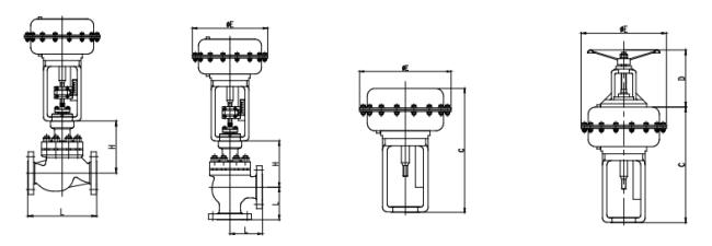
GLOBE
Body Size |
L | H | |||||||
| ANSI150LB | ANSI300LB | ANSI600LB | Fin- Extension type |
||||||
| INCH | DN | RF RJ | Welded |
RF RJ | Welded |
RF RJ | Welded |
||
| 1/2 | 15 | 184 | 206 | 190 | 206 | 203 | 206 | 124 | 224 |
| 3/4 | 20 | 184 | 210 | 194 | 210 | 206 | 210 | 124 | 224 |
| 1 | 25 | 184 | 210 | 197 | 210 | 210 | 210 | 124 | 224 |
Body Size |
L | H | |||||||
| ANSI900LB | ANSI1500LB | ANSI2500LB | Fin- Extension type |
||||||
| INCH | DN | RF RJ | Welded |
RF RJ | Welded |
RF RJ | Welded |
||
| 1/2 | 15 | 292 | 292 | 292 | 292 | 318 | 318 | 160 | 260 |
| 3/4 | 20 | 292 | 292 | 292 | 292 | 318 | 318 | 160 | 260 |
| 1 | 25 | 292 | 292 | 292 | 292 | 318 | 318 | 160 | 260 |
ANGLE
Body Size |
L | H | |||||||
| ANSI150LB | ANSI300LB | ANSI600LB | Fin-Extension type |
||||||
| INCH | DN | RF RJ |
Welded |
RF RJ |
Welded |
RF RJ | Welded |
||
| 1/2 | 15 | 92 | 103 | 95 | 103 | 102 | 103 | 124 | 224 |
| 3/4 | 20 | 92 | 105 | 97 | 105 | 103 | 105 | 124 | 224 |
| 1 | 25 | 92 | 105 | 99 | 105 | 105 | 105 | 124 | 224 |
Body Size |
L | H | |||||||
| ANSI900LB | ANSI1500LB | ANSI2500LB | Fin-Extension type |
||||||
| INCH | DN | RF RJ |
Welded |
RF RJ |
Welded |
RF RJ | Welded |
||
| 1/2 | 15 | 196 | 196 | 196 | 196 | 159 | 159 | 160 | 260 |
| 3/4 | 20 | 196 | 196 | 196 | 196 | 159 | 159 | 160 | 260 |
| 1 | 25 | 196 | 196 | 196 | 196 | 159 | 159 | 160 | 260 |
Actuator Size |
E | C | D | F |
| 250 | 252 | 343 | 168 | - |
| 290 | 292 | 369 | 214 | - |
| 370 | 370 | 409 | 214 |
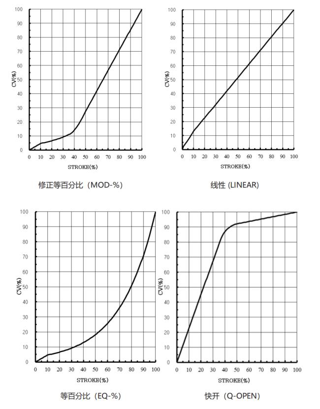
FLOW CHARACTERISTICS
Similar Products
Get in Touch
Have questions about our products or want to discuss a custom order? Our team is ready to help you.
Company
WEYO AUTO TECH
Location
Room Milton103, Building 5 - 2, Lane 658, Jinzhong Road, Changning District, Shanghai.
Contact Person
flnn