
Small Bore Single Seat Control Valve 20mm 25mm ANSI 125 150 300 600
The HLS small-bore single-seat control valve can be used to control fluids with various pressures and temperatures. The valve body has an S-streamline channel, featuring small pressure drop loss, large flow capacity, wide adjustable range, and high flow characteristic accuracy. The control valve is equipped with a multi-spring diaphragm actuator, which has a compact structure and large output force.
Trim
| Plug Type | Single-seat Plunger-type Plug |
| Flow Characteristics |
Metal Seat: High-precision flow characteristics with Cv values from 0.4 to 14 comply with IEC534-2. Refer to Figure 1. Soft Seat: For Cv values from 0.4 to 14, refer to Figure 2. |
| Operating Range | For the operating temperature and pressure differential of the soft seat, refer to Figure 4. For the operating temperature and pressure differential of Stellite overlay, refer to Figure 5 |
| Materials | 1Cr18Ni9, Stellite alloy overlay, 9Cr18MoV |
Actuator
| Type | HA Multi-spring Diaphragm Actuator |
| Diaphragm Material | EPDM with Nylon Insert |
| Spring Range | 0.02 to 0.10, 0.08 to 0.24 MPa |
| Supply Pressure | 0.14, 0.16, 0.28, 0.40 MPa |
| Air Supply Connection | Rc 1/4 |
| Ambient Temperature |
-30~+70℃
|
| Valve Action Type | Air-to-Open or Air-to-Close |
| Accessories | Positioner, Handwheel Mechanism, Pneumatic Valve Position Transmitter |
Leakage Rate
| Metal Seat | Complies with ANSI B16.104 Class IV, ≤ 0.01% of rated Cv |
| Soft Seat | Complies with ANSI B16.104 Class VI, ≤ 10⁻⁷ of rated Cv |
| Quick-Opening Plug | ≤ 0.00001% of rated Cv |
| Adjustable Range | 50∶1 (Cv ≥ 1.0) or 30∶1 (Cv ≤ 0.63) |
Cv Value and Stroke, see Table 1.
| Plug Type | Seat and Flow Characteristics | Stroke | 0.01 | 0.04 | 0.1 | 0.16 | 0.25 | 0.4 | 0.63 | 1.0 | 1.6 | 2.5 | 4.0 | 6.3 | 10 |
14 |
||
| Piston Plug | Metal Seat | Equal percentage (%) |
14.3 |
○ | △ | △ | △ | △ | △ | △ | △ | △ | △ | |||||
| linear (L) | ○ | ○ | ○ | ○ | ○ | △ | △ | △ | △ | △ | △ | △ | △ | △ | ||||
| Soft Seat | Equal percentage (%) | ○ | ○ | ○ | ○ | ○ | ○ | ○ | ○ | ○ | ○ | |||||||
| linear (L) | ○ | ○ | ○ | ○ | ○ | ○ | ○ | ○ | ○ | ○ | ○ | ○ | ||||||
| Quick-Opening Plug | Stellite Overlay Seat (QS) | 6.0 | ○ | ○ | ||||||||||||||
|
Nominal Diameter (mm): 20 25 |
←———————————————————→ ←—————————————————————→ |
|||||||||||||||||
Figure 1 High-precision flow characteristic curves (Cv = 0.4 to 14)
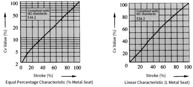
Figure 2 Flow characteristic curves of plunger-type plug (Cv = 0.4 to 14)
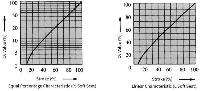
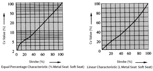
Figure 3 Flow characteristic curves of plunger-type plug (Cv = 0.01 to 0.25)
I. Metal Seat, see Table 2.
| Mode of Action | Actuator | Supply Pressure(Mpa) | Spring Rang(Mpa) | Positioner | Allowable Pressure Differential(Mpa) | |||||||||
| Rated Cv Value | ||||||||||||||
| ≤0.25 | 0.4 | 0.63 | 1.0 | 1.6 | 2.5 | 4.0 | 6.3 | 10 | 14 | |||||
| Air-to-Close | HA2D | 0.14 | 0.02~0.10 | With or Without |
4* 10 |
4* 6.2 |
4* 6.2 |
3.26 | 3.26 | 2 | 2 | 1.09 | 0.82 | 0.5 |
| 0.16 | 0.02~0.10 | With | - |
4* 10 |
4* 10 |
4* 10 |
4* 10 |
4* 10 |
4* 10 |
4* 5.4 |
4 | 2.52 | ||
| 0.40 | 0.08~0.24 | With | - | - | - | - | - | - | - |
4* 10 |
4* 10 |
4* 7.5 |
||
| Air-to-Open | HA2R | 0.14 | 0.02~0.10 | With or Without |
4* 10 |
4* 6.2 |
4* 6.2 |
3.26 | 3.26 | 2 | 2 | 1.09 | 0.82 | 0.50 |
| 0.28 | 0.08~0.24 | With | - |
4* 10 |
4* 10 |
4* 10 |
4* 10 |
4* 10 |
4* 10 |
4* 7.6 |
4* 5.6 |
3.5 | ||
Remarks:
1.The maximum allowable pressure difference shall not exceed the maximum working pressure specified in ANSI B16.34
or JIS B2201 standards.
2.In the same cell, the upper value is the allowable pressure difference when the valve is fully open, and the lower value
indicates the allowable pressure difference when the valve is fully closed.
3.For allowable pressure differences marked with *, when the valve controls liquid, the allowable pressure difference shall
be limited to 3 MPa. If it exceeds 3 MPa, please select HLC control valves.
II. Soft Seat, see Table 3.
| Mode of Action | Actuator | Supply Pressure(Mpa) |
Spring Rang(Mpa) |
Positioner | Allowable Pressure Differential(Mpa) | |||||||||
| Rated Value | ||||||||||||||
|
≤0.25
|
0.4
|
0.63 | 1.0 | 1.6 | 2.5 | 4.0 | 6.3 | 10 | 14 | |||||
| Air-to-Close | HA2D | 0.14 | 0.02~0.10 | With or Without | 2 | 2 | 2 | 2 | 2 | 1.4 | 1.4 | 0.76 | 0.57 | 0.35 |
| 0.16 | 0.02~0.10 | With | - | 3 | 3 | 3 | 3 | 3 | 3 | 3 | 2.8 | 1.76 | ||
| 0.40 | 0.08~0.24 | With | - | - | - | - | - | - | - | 3 | 3 | 3 | ||
| Air-to-Open | HA2R | 0.14 | 0.02~0.10 | With or Without | 2 | 2 | 2 | 2 | 2 | 1.4 | 1.4 | 0.76 | 0.57 | 0.35 |
| 0.28 | 0.08~0.24 | With | - | 3 | 3 | 3 | 3 | 3 | 3 | 2 | 3 | 2.4 | ||
Remarks: The maximum allowable pressure differential shall not exceed the maximum working pressure specified in
ANSI B16.34 and JIS B2201 standards.
III. Stellite Overlay Quick-Opening Plug (Metal Seat QS), see Table 4.
| Mode of Action | Actuator | Supply Pressure(Mpa) | Spring Rang(Mpa) | Allowable Pressure Differential(Mpa) | |
| Rated Cv Value | |||||
| 10 | 14 | ||||
| Air-to-Close | HA2D | 0.14 | 0.02~0.053 | 1.46 | 1.3 |
| 0.30 | 0.02~0.053 | 4.0 | 3.7 | ||
| Air-to-Open | HA2R | 0.14 | 0.04 | 0.67 | 0.60 |
| 0.28 | 0.08 | 1.35 | 1.21 | ||
Remarks: The maximum allowable pressure difference shall not exceed the maximum working pressure specified in
ANSI B16.34 and JIS B2201 standards.
Flange Distance
| Nominal Diameter | A | ||||||||||
|
ANSI 125 FF
ANSI 150 RF
JIS 10K FF RF
PN 1.6 MPa
|
JIS
16K
RF
|
ANSI 300
JIS 20,30K RF
PN 4.0MPa
|
ANSI 600
JIS 40K RF
PN6.4 MPa
|
ANSI
150
RJ
|
ANSI
300
RJ
|
ANSI
600
RJ
|
JIS
20K
LG
|
JIS
30K
LG
|
ANSI
300
LG
|
ANSI
600
SW,BW
|
|
| 20 | 184 | 190 | 194 | 206 | 206 | 206 | 198 | 208 | 203 | 206 | |
| 25 | 184 | 193 | 197 | 210 | 197 | 210 | 210 | 198 | 212 | 206 | 210 |
| Actuator | H | φB | C | E | |||||
| P | E1 | E2 | |||||||
| E21 | E2W | ||||||||
| HA2D,R | 450 | 600 | 760 | 975 | 267 | 281 | 40 | ||
Note: P = normal temperature type, E1 = extended type I, E2 = extended type II, E21 = integral type, E2W = welded type
| Connection form | Nominal pressure | P | E1 | E2 | |||||
| E21 | E2W | ||||||||
| Flange | ANSI 125150 JIS 10K |
23 | 25 | 28 | 33 | ||||
| ANAI 300600 JIS 16203040K |
24 | 26 | 29 | 34 | |||||
| welding SW | 21 | 23 | 26 | 31 | |||||
Note: P = normal temperature type, E1 = extended type I, E2 = extended type II, E21 = integral type, E2W = welded type
Get in Touch
Have questions about our products or want to discuss a custom order? Our team is ready to help you.