
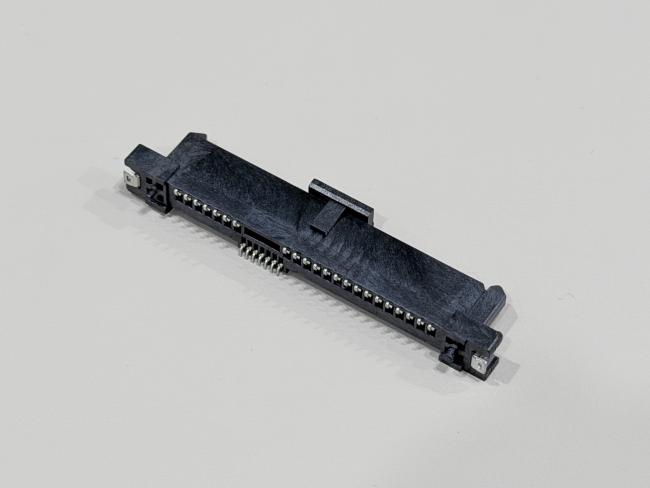
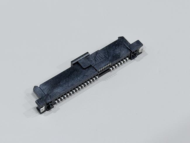
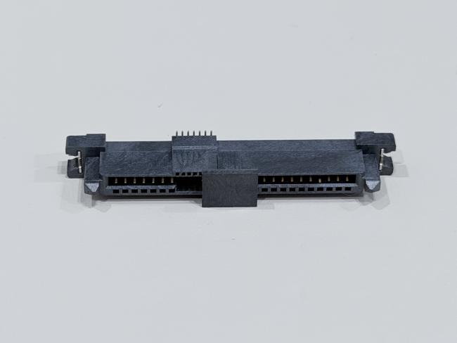
SAS 29P SMT Female Connector 1.27mm Pitch, 30U" Gold-Plated Electronic Signal & Power PCB Connector
• Free samples available for quality evaluation.
• Support for both OEM & ODM customization.
• Trade Terms: EXW, FOB, CIF, CPT, etc.
This SAS 29P SMT female connector is a compact, high-reliability electronic connector designed for high-speed signal and low-power transmission in servers, storage systems and industrial equipment. With a 1.27mm pitch and full SMT PCB mounting, it supports dense routing on multilayer boards and is suitable for automated reflow assembly.
The contact system uses phosphor bronze C5191-H terminals with a multi-layer plating structure: 50µ" nickel underplate for corrosion resistance, 30µ" gold on selected contact areas to ensure stable low contact resistance for high-speed data lines, and 80µ" matte tin on the solder area to provide strong, reliable solder joints to PCB pads. Plated brass positioning pegs help align the connector accurately during placement and improve mechanical retention on the board.
Electrically, the connector is rated at 1.5A @ 40VAC, with contact resistance ≤30mΩ, insulation resistance ≥1000MΩ and a withstand voltage of 500VAC per minute. Mechanically, it offers defined mating and unmating forces, and up to 500 mating cycles on the backplane side according to EIA 364-09, while a 48-hour gold-area salt-spray test verifies its resistance to harsh environments.
Thanks to its SMT structure, 30U" gold-plated terminals and halogen-free RoHS 2.0 compliant materials, this SAS 29-pin female connector is an ideal choice for customized wire and cable assemblies, PCB interconnects and high-density designs in server, automotive and power-electronic transmission applications.
| Product Type | SAS 29P SMT straight female connector, 30U" gold-plated |
| Interface Series | SAS series (29-pin female) |
| Number of Positions | 29 pins (7 + 7 signal pins, 15 power/ground pins) |
| Pitch of Housing | 1.27mm (typical SAS pitch) |
| Gender | Female connector |
| Mounting Style | SMT (surface-mount to PCB) with positioning pegs |
| Rated Current / Voltage | 1.5A @ 40VAC |
| Operating Temperature | –20°C to +85°C |
| Contact Resistance | ≤ 30mΩ (Max) |
| Insulation Resistance | ≥ 1000MΩ (Min) |
| Withstand Voltage | 500VAC / minute |
| Mating Force | Backplane ≤ 25N Max |
| Unmating Force | Backplane ≥ 5N Min |
| Mating Durability | Up to 200 cycles/hour; backplane 500 cycles max (per EIA 364-09) |
| Salt Spray Test | Gold-plated area ≥ 48 hours |
| Terminal Base Material | Phosphor Bronze C5191-H, t = 0.25mm (TS-C07F-M21 / TS-007F-M08 / TS-C15F-M14) |
| Terminal Plating – Underlayer | Ni 50µ" min plated on terminals |
| Terminal Plating – Contact Areas | Combination of Ni 50µ" min and Au 30µ" plated on contact area for selected pins |
| Terminal Plating – Solder Area | Matte Sn 80µ" min plated on solder area (for SMT pads) |
| Peg Material | Brass C2680-H, t = 0.30mm, Ni 50µ" min + Matte Sn 80µ" min plated (TG-C29F-002) |
| Housing Material | LCP G/F Black UL94-V0 (HSS-C29F-031) |
| Cap Material | LCP G/F Black UL94-V0 (CAP-C29F-003) |
| Environmental Compliance | HF (Halogen-Free) + RoHS 2.0 compliant |
| Typical Connection | High-speed SAS signal and low-power transmission between PCB and cable/board in electrical and electronic systems |
⚙️ Applications
- Server & Data Center Equipment – Used as SAS / SATA electronic signal and power connectors on HDD/SSD backplanes, RAID cards, JBOD/NAS and 1U/2U server boards.
- Communication & Networking Systems – For routers, switches, base stations and other networking equipment that need compact PCB connectors and reliable high-speed transmission.
- Industrial & Automation Electronics – Applied in industrial PCs, PLCs, motion controllers, data loggers and test instruments as PCB-to-wire or cable connectors.
- Automotive & New Energy Applications – Used in in-vehicle data recorders, infotainment units, EV chargers and energy-storage systems for signal and low-power transmission.
- Custom Wire Harness & Cable Assemblies – Suitable for OEM/ODM projects that require connector customization for PCB, wire and cable layouts in electrical and electronic devices.
⚠️ Notes
- Make sure the working voltage, current and temperature of your design stay within the connector’s rated values, with proper safety margin.
- Design PCB pads, holes and mechanical space according to the drawing and pitch, and avoid bending or twisting stress on the connector after soldering or assembly.
- Select appropriate wire gauge, insulation and cable structure based on current load, signal speed and bending requirements for both power and signal terminals.
- For IDC / crimp types, use matched tooling and press-force to ensure full insulation displacement; for solder types, follow a controlled soldering profile to avoid overheating the LCP housing.
- Insert and pull out the connector along the mating direction, avoid pulling on the cable itself, and do not exceed the specified mating/unmating force or durability cycles.
- Keep gold-plated contact areas clean and dry, avoid touching them with bare fingers, and store products in dry anti-static packaging before assembly.


Get in Touch
Have questions about our products or want to discuss a custom order? Our team is ready to help you.