
High-Reliability SATA 13Pin 180° Solder Wire Female Connector 1.27mm Pitch | Electrical Signal & Power Terminal Connector for Server, Automotive Wire Cable & Custom Harness Transmission
• Free samples available for quality evaluation.
• Support for both OEM & ODM customization.
• Trade Terms: EXW, FOB, CIF, CPT, etc.
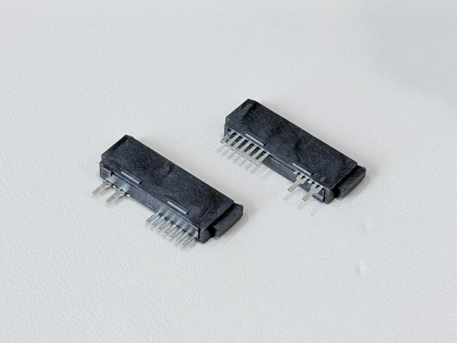
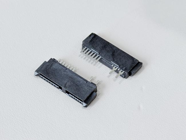
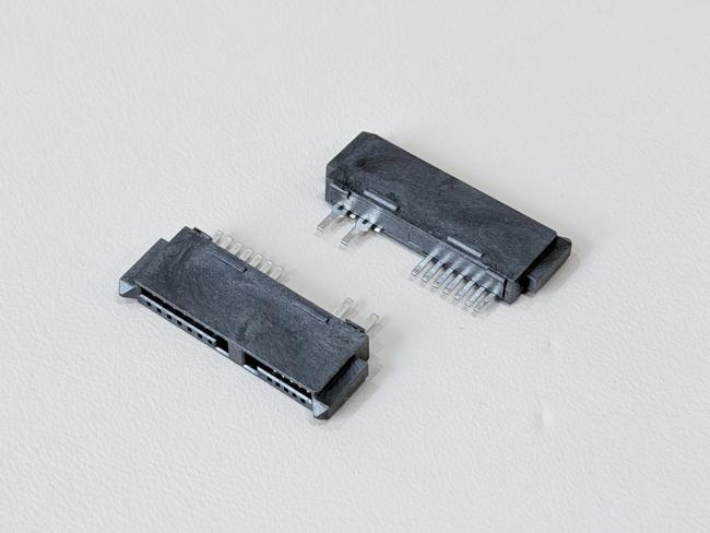
The SATA 13P 180° solder wire female connector is designed for compact, high-reliability wire cable and harness applications where stable electrical performance and secure mechanical retention are critical. With a 1.27mm pitch and 13-pin SATA interface, it supports combined electronic signal and low-power transmission in storage devices, servers, automotive modules and industrial controllers.
Terminals are made from phosphor bronze C5191-H and finished with a robust plating stack: 50µ" nickel under-layer, 15µ" gold flash (G/F) on the contact area to maintain low contact resistance, and 80µ" matte tin on the solder area for strong bonding to copper wires. The connector is rated at 1.5A @ 40VAC, with contact resistance ≤30mΩ, insulation resistance ≥1000MΩ, and withstand voltage 500VAC / minute, ensuring reliable performance in dense electrical and electronic systems.
Mechanically, the 180° solder-wire structure and reinforced housing deliver controlled mating/unmating forces and a single-pin retention force ≥0.8kgf, improving resistance to vibration and wire pull in cable assemblies. The black UL94-V0 glass-filled LCP housing offers excellent heat resistance and dimensional stability, making the connector suitable for automated soldering and crimping processes.
With RoHS-compliant materials, support for customized wire gauge, cable length and harness routing, this SATA 13Pin 180° solder wire female connector is an ideal choice for OEMs needing dependable connector-to-wire solutions for server, automotive, PCB-to-cable and other electrical transmission applications.
| Product Type | SATA 13P 180° solder-wire female connector, Au 15µ" gold-plated |
| Interface Series | SATA series, 13-pin female connector |
| Number of Positions | 13 pins |
| Pitch of Housing | 1.27mm (C: 1.27 pitch) |
| Termination Style | 180° solder way of terminal with wire (wire cable connection, no PCB tail) |
| Application Type | Electrical / electronic wire cable & harness connector for signal and power transmission |
| Rated Current / Voltage | 1.5A @ 40VAC |
| Operating Temperature | –20°C to +85°C |
| Contact Resistance | ≤ 30mΩ (Max) |
| Insulation Resistance | ≥ 1000MΩ (Min) |
| Withstand Voltage | 500VAC / minute |
| Mating Force | ≤ 45N Max |
| Unmating Force | ≥ 15N Min (1–5 cycles), ≥ 10N Min (6–50 cycles) |
| Single Pin Retention | ≥ 0.8kgf per pin |
| Terminal Material | Phosphor Bronze C5191-H, t = 0.25mm (TS-A06F-S09, TS-C07F-S07) |
| Terminal Plating | Ni 50µ" Min under-plating; Au 15µ" G/F on contact area; Sn 80µ" Min on solder area |
| Housing Material | LCP G/F Black UL94-V0 (HSS-C13F-A09) |
| Environmental Compliance | RoHS 2.0 compliant |
| Typical Uses | Server & storage SATA cable, automotive wire harness, custom electrical wire cable assemblies, electronic signal & low-power transmission |
⚙️ Applications
- Server & Data Center Equipment – Used as SAS / SATA electronic signal and power connectors on HDD/SSD backplanes, RAID cards, JBOD/NAS and 1U/2U server boards.
- Communication & Networking Systems – For routers, switches, base stations and other networking equipment that need compact PCB connectors and reliable high-speed transmission.
- Industrial & Automation Electronics – Applied in industrial PCs, PLCs, motion controllers, data loggers and test instruments as PCB-to-wire or cable connectors.
- Automotive & New Energy Applications – Used in in-vehicle data recorders, infotainment units, EV chargers and energy-storage systems for signal and low-power transmission.
- Custom Wire Harness & Cable Assemblies – Suitable for OEM/ODM projects that require connector customization for PCB, wire and cable layouts in electrical and electronic devices.
⚠️ Notes
- Make sure the working voltage, current and temperature of your design stay within the connector’s rated values, with proper safety margin.
- Design PCB pads, holes and mechanical space according to the drawing and pitch, and avoid bending or twisting stress on the connector after soldering or assembly.
- Select appropriate wire gauge, insulation and cable structure based on current load, signal speed and bending requirements for both power and signal terminals.
- For IDC / crimp types, use matched tooling and press-force to ensure full insulation displacement; for solder types, follow a controlled soldering profile to avoid overheating the LCP housing.
- Insert and pull out the connector along the mating direction, avoid pulling on the cable itself, and do not exceed the specified mating/unmating force or durability cycles.
- Keep gold-plated contact areas clean and dry, avoid touching them with bare fingers, and store products in dry anti-static packaging before assembly.


Get in Touch
Have questions about our products or want to discuss a custom order? Our team is ready to help you.