
High-Reliability SATA 13Pin 180° Wire Solder Female Connector 1.27mm Pitch | Electrical Signal & Power Terminal Connector for Server, Automotive & Custom Wire Cable Transmission
• Free samples available for quality evaluation.
• Support for both OEM & ODM customization.
• Trade Terms: EXW, FOB, CIF, CPT, etc.
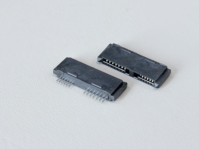
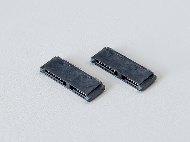
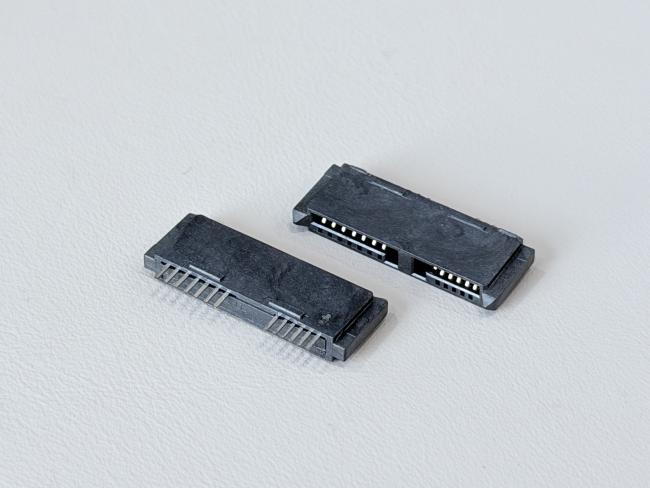
This SATA 13P 180° DIP female connector is designed for reliable PCB mounting in high-density electronic systems. With a 1.27mm pitch and 13-pin SATA interface, it supports combined signal and power transmission on compact boards used in servers, storage devices, industrial controllers and automotive electronics.
The terminals are made from phosphor bronze C5191-H (0.25mm) and adopt a robust multi-layer plating structure: 50µ" nickel underplate for corrosion protection, gold G/F on the contact area to keep low contact resistance for high-speed SATA signals, and 80µ" matte tin on the solder tails for strong and stable through-hole soldering to the PCB. Rated at 1.5A @ 40VAC with ≤30mΩ contact resistance, ≥1000MΩ insulation resistance and 500VAC withstand voltage, the connector ensures stable electrical performance in demanding environments.
Mechanically, the 180° DIP tail design and reinforced LCP housing provide controlled mating force (≤45N), reliable unmating force after 500 mating cycles and a single-pin retention force ≥0.8kgf, improving resistance to vibration and mechanical shock on the board. The black UL94-V0 glass-filled LCP housing offers excellent heat resistance and dimensional stability, making this connector well-suited for automated soldering and assembly processes.
With RoHS 2.0-compliant materials and the ability to integrate into customized PCB layouts, this SATA 13Pin 180° DIP female connector is an ideal choice for OEMs seeking compact, high-reliability electrical and electronic connector solutions in server, storage, industrial and automotive applications.
| Product Type | SATA 13P 180° DIP-type female connector, gold-plated G/F |
| Interface Series | SATA series, 13-pin female PCB connector |
| Number of Positions | 13 pins |
| Pitch of Housing | 1.27mm (C: 1.27 pitch) |
| Termination Style | 180° DIP way of terminal to PCB (through-hole tails) |
| Application Type | PCB signal & power connector for electrical / electronic equipment |
| Rated Current / Voltage | 1.5A @ 40VAC |
| Operating Temperature | –20°C to +85°C |
| Contact Resistance | ≤ 30mΩ (Max) |
| Insulation Resistance | ≥ 1000MΩ (Min) |
| Withstand Voltage | 500VAC / minute |
| Mating Force | ≤ 45N Max |
| Unmating Force | ≥ 2.5N Min after 500 cycles |
| Single Pin Retention Force | ≥ 0.8kgf per pin |
| Terminal Base Material | Phosphor Bronze C5191-H, t = 0.25mm (TS-A06F-S31, TS-C07F-S35) |
| Terminal Plating – Underlayer | Ni 50µ" Min plated over terminal |
| Terminal Plating – Contact Area | Au G/F plated on contact area |
| Terminal Plating – Solder Area | Tin 80µ" Min plated on solder area |
| Housing Material | LCP G/F Black UL94-V0 (HSS-C13F-A14) |
| Salt-Spray Performance | Gold area ≥ 48h |
| Environmental Compliance | RoHS 2.0 compliant |
| Typical Uses | PCB signal / power transmission in servers, storage devices, industrial control, automotive electronics and customized PCB assemblies |
⚙️ Applications
- Server & Data Center Equipment – Used as SAS / SATA electronic signal and power connectors on HDD/SSD backplanes, RAID cards, JBOD/NAS and 1U/2U server boards.
- Communication & Networking Systems – For routers, switches, base stations and other networking equipment that need compact PCB connectors and reliable high-speed transmission.
- Industrial & Automation Electronics – Applied in industrial PCs, PLCs, motion controllers, data loggers and test instruments as PCB-to-wire or cable connectors.
- Automotive & New Energy Applications – Used in in-vehicle data recorders, infotainment units, EV chargers and energy-storage systems for signal and low-power transmission.
- Custom Wire Harness & Cable Assemblies – Suitable for OEM/ODM projects that require connector customization for PCB, wire and cable layouts in electrical and electronic devices.
⚠️ Notes
- Make sure the working voltage, current and temperature of your design stay within the connector’s rated values, with proper safety margin.
- Design PCB pads, holes and mechanical space according to the drawing and pitch, and avoid bending or twisting stress on the connector after soldering or assembly.
- Select appropriate wire gauge, insulation and cable structure based on current load, signal speed and bending requirements for both power and signal terminals.
- For IDC / crimp types, use matched tooling and press-force to ensure full insulation displacement; for solder types, follow a controlled soldering profile to avoid overheating the LCP housing.
- Insert and pull out the connector along the mating direction, avoid pulling on the cable itself, and do not exceed the specified mating/unmating force or durability cycles.
- Keep gold-plated contact areas clean and dry, avoid touching them with bare fingers, and store products in dry anti-static packaging before assembly.


Get in Touch
Have questions about our products or want to discuss a custom order? Our team is ready to help you.