
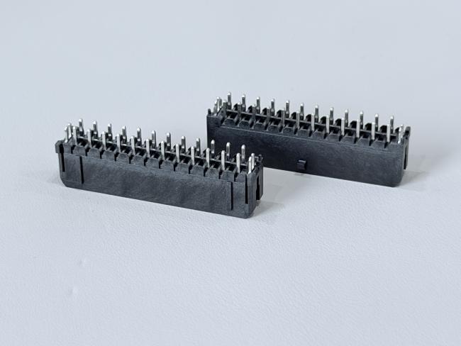
Micro-Fit 3.0 Pin Header 3.0mm Pitch 2×12 Vertical PCB Power & Signal tyco Connector with Peg, Tin-Plated Terminals for Automotive, Server & IDC Wire
• Free samples available for quality evaluation.
• Support for both OEM & ODM customization.
• Trade Terms: EXW, FOB, CIF, CPT, etc.
This Micro-Fit 3.0 2×12 pin header connector is optimized for high-density, high-current power and signal transmission on compact PCBs.
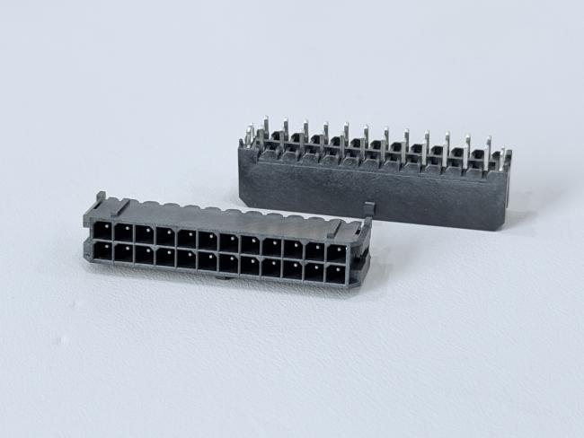
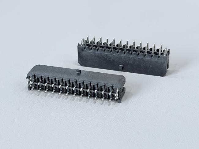
The 3.0 mm pitch, dual-row 24-pin layout provides abundant circuits for mixed power and control signals while keeping the footprint small. Square copper-alloy pins and stamped solder tabs are finished with 50 μ" nickel and 100 μ" tin plating, delivering low contact resistance, strong solderability and excellent corrosion resistance even after 24-hour salt-spray testing.
With a rated current of 12.5 A per circuit at 250 V AC/DC, this connector is ideal for low-voltage power rails and robust signal links.
The vertical through-hole structure with locating peg ensures accurate PCB positioning and strong mechanical anchoring, maintaining stability under vibration, cable pull and repeated mating cycles. Glass-fiber-reinforced LCP housings rated UL94 V-0 and halogen-free withstand lead-free soldering profiles and an operating temperature range of −40 °C to +105 °C, making the connector suitable for harsh industrial and automotive environments.
| Product type | Micro-Fit 3.0 pin header connector (male) |
| Function | Wire-to-board electrical / electronic power & signal transmission |
| Series / pitch | Micro-Fit 3.0, 3.0 mm pitch |
| Positions | 2×12 pins (24 pins), dual row |
| Mounting style | Vertical through-hole PCB, with locating peg/post, external pin length 3.2 mm |
| Pin terminal material | Copper alloy C1100 square pins |
| Fish-tail / solder tab material | Copper alloy C2680-H, t=0.45 mm |
| Plating | Ni 50 μ" min under-plating, matte Sn 100 μ" min on terminals |
| Rated current | Up to 12.5 A per circuit with AWG16 wire |
| Rated voltage | 250 V AC / DC |
| Contact resistance | ≤ 20 mΩ max |
| Insulation resistance | ≥ 1000 MΩ min |
| Dielectric withstand | 1500 V AC / minute |
| Salt-spray test | 24 h |
| Operating temperature | −40 °C to +105 °C |
| Pin retention force | ≥ 1.5 Kgf per pin before and after reflow |
| Housing material | LCP E130I black, G/F reinforced, UL94 V-0, halogen-free |
| Cap / insulator | LCP black G/F, UL94 V-0 |
| Environmental | HF, RoHS-compliant |
| Typical mating | Micro-Fit 3.0 style female housing & crimp / IDC terminals, custom wire harness |
⚙️ Applications
- PCB Signal & Data Transmission: Used for board-to-board or board-to-module connections, including low-voltage signals, data transmission, and control interfaces.
- Consumer Electronics: Common in smart home appliances, printers, cameras, displays, controllers, and handheld devices for internal signal routing.
- Industrial Automation & Control Systems: Applied in PLCs, industrial control boards, sensors, meters, robotics modules, and automation I/O interfaces.
- Servers & Data Center Equipment: Used for backplane interfaces, storage modules, communication boards, and signal expansion connectors.
- Automotive Electronics: Suitable for ECUs, BMS modules, sensor units, dashboards, infotainment systems, and on-board control interfaces.
- Communication & Networking Devices: Used in routers, switches, IoT gateways, RF modules, and network communication cards.
- IoT & Smart Device Modules: Applied in Bluetooth modules, WiFi modules, GPS/Beidou modules, sensor nodes, and embedded system expansion ports.
- Power Control & Monitoring Boards: For auxiliary power transmission, monitoring signals, and low-power control circuits.
- Custom OEM/ODM Electronic Designs: Ideal for designs requiring customizable pin count, pitch, height, plating option, and configuration.
⚠️ Notes
- Ensure Correct Pin Alignment: Check orientation and positioning before mating to avoid mis-insertion, bent pins, or PCB pad damage.
- Do Not Exceed Electrical Ratings: Follow the specified current and voltage limits to prevent overheating or contact failure.
- Proper Insertion and Extraction Force: Avoid excessive force during mating/unmating to prevent deformation, cracked solder joints, or pin damage.
- Keep Contact Surfaces Clean: Ensure terminals remain free from dust, oil, oxidation, or contaminants that reduce conductivity.
- Follow Recommended Soldering Conditions: Use appropriate soldering temperature profiles according to plastic materials such as LCP, PA6T, PA66, or PBT.
- Verify PCB Hole Tolerance: Incorrect hole size may cause inadequate solder filling or mechanical instability.
- Avoid Mechanical Stress After Assembly: Do not apply lateral pressure or bending forces, especially for SMT pin headers.
- Maintain Proper Storage Conditions: Store in a dry, dust-free environment to prevent terminal oxidation; use anti-static packaging if required.
- Confirm Compatibility with Female Header: Ensure matching pitch, pin count, height, and contact design to avoid mating failure.
- Choose Correct Plating Specification: Select proper plating (gold, tin, nickel) based on your application’s durability, corrosion resistance, and signal reliability needs.


Get in Touch
Have questions about our products or want to discuss a custom order? Our team is ready to help you.